

Important information
This manual applies to VistaSoft, order number: 2110100003, version 3.0.30 or higher.
This manual forms part of the software. It corresponds to the version of the software and the technical standards valid at the time of installation.
In the event of non-compliance with the instructions and information contained in this manual, the manufacturer and the distributor will not offer any guarantee or accept any liability for the safe operation and the safe functioning of the unit and the software.
The German version of the instructions is the original manual. All other languages are translations of the original manual.
All circuits, processes, names, software programs and units mentioned in this document are protected by copyright.
The Installation and Operating Instructions must not be copied or reprinted, neither in full nor in part, without written authorisation from the copyright owner.
Warnings and symbols
The warnings in this document are intended to draw your attention to possible injury to persons or damage to machinery.
The following warning symbols are used:

General warning symbol
The warnings are structured as follows:

NOTICE
Description of the type and source of danger
Here you will find the possible consequences of ignoring the warning
Follow these measures to avoid the danger.
DANGER
Immediate danger of severe injury or death
WARNING
Possible danger of severe injury or death
CAUTION
Risk of minor injuries
NOTICE
Risk of extensive material/property damage
These symbols are used in the document and on or in the unit:
Note, e.g. specific instructions regarding efficient and cost-effective use of the unit.

Refer to the accompanying electronic documents.

CE labelling with the number of the notified body

Medical device

Order number

Lot designation

Health Industry Bar Code (HIBC)

Manufacturer
Action instructions are identified specifically in this document:
Safety
The software has been developed to rule out virtually all dangers when it is used properly and in accordance with its intended use.
Despite this, the following residual risks can remain:Personal injury due to incorrect use/misuse
Personal injury due to malfunction
Classification
Classification | ||
|---|---|---|
Medical Device Class | IIb |
Intended purpose
The software features functions for recording, displaying, analysing, diagnosing, managing and sending digital or digitised 2D and 3D images and videos in dental practices and specialist dental clinics.
Intended use
The software is intended for the viewing and diagnosis of image data in relation to dental issues. Its proper use is documented in the operating instructions of the corresponding image-generating systems.
Image-generating systems that can be used with the software include optical video cameras, digital X-ray cameras, image plate scanners, extraoral X-ray devices, intraoral scanners and TWAIN compatible image sources.The software must only be used by authorized healthcare professionals in dental areas for the following tasks:Filter optimisation of the display of 2D and 3D images for improved diagnosis
Acquisition, storage, management, display, analysis, editing and supporting diagnosis of digital/digitised 2D and 3D images and videos
Forwarding of images and additional data to external software (third-party software)
The software is not intended for mammography use.
Improper use
Performance of measurements on images that are not suitable for this purpose due to the way in which the images were created. The software does not provide a measuring function due to the unavoidable geometric image properties of X-ray images. Here, displayed values are only intended to serve as guide values. This also applies after use of the calibration function.
Use for contraindicated purposes for the image-generating system. The operating instructions of the image-generating system must be followed here.
Any other usage or usage beyond this scope is deemed to be improper. The manufacturer accepts no liability for damages resulting from this. In these cases the user/operator will bear the sole risk
The software is not intended for mammography use.
Functions
The patient data can be copied from external programs via defined interfaces.
The 2D or 3D image data is saved for the selected patient in a database and can be displayed in an optimised manner to help with diagnosis. Different views for reconstructed X-ray image layers (MPR) and 3D volumes from 3D image data are available.Image data can be imported and exported in various graphics formats together with the metadata or sent to external programs via defined interfaces.VistaSoft can be used both as a single workstation system and as a multi-station system in client/server operation.Specialist personnel
Make sure every operator is trained in the use of the software.
Have the manufacturer or a qualified company authorised by the manufacturer perform mounting, new installations, modifications, expansions and repairs.
Protection from threats from the Internet
The software is installed on a computer connected to the Internet. Therefore, the system needs to be protected from threats from the Internet.
Use antivirus software and update it regularly.
Look for evidence of possible virus infection and, if applicable, check with the antivirus software and remove the virus.
Use, properly configure and regularly update your firewall.
Update the computers operating system regularly.
Perform regular data backups.
Provide access to computers to authorised users only, e.g. by means of user name and password.
Make sure that only trustworthy content is downloaded. Only install software and firmware updates that have been authenticated by the manufacturer.
Using the software in an IT network
Running the software in an IT network can lead to previously unknown risks for patients, users and third parties.
It is recommended that you identify, analyse, evaluate and control these risks. Apply the IEC 80001‑1 standard for risk assessment.
Incorrect manual configuration can lead to significant network problems. The expert knowledge of a network administrator is required for configuration.
If, for example, the following changes are made to the network, new risks can arise that require further analysis.- Changes in the IT network configuration
- Adding components (hardware or software) to the IT network
- Removing components from the IT network
- "Updating" components in the IT network
- "Upgrading" components in the IT network
Notification requirement of serious incidents
The operator/patient is required to report any serious incident that occurs in connection with the device to the manufacturer and to the competent authority of the Member State in which the operator and/or patient is established/resident.
Software license agreement (EULA)
between
DÜRR DENTAL SEHöpfigheimer Str. 17D-74321 Bietigheim-Bissingenandyou as the UserFor the current End User Licensing Agreement (EULA), please refer to Installation Process.
§1 Object of the Agreement
(1) The object of this Agreement is the Dürr Dental VistaSoft software, drivers and interfaces with all associated program components, as well as - as per agreement - additional modules for the VistaSoft software (“Software"). (2) Dürr Dental SE grants the right of use to the rightfully acquired Software to the User for the duration of this agreement and in accordance with the following provisions. The Software is protected by copyright (§§ 69 a pp UrhG [German Copyright Protection Act]). (3) Articles 5 and 6 (warranty and liability) do not apply if the User does not acquire the Software directly from Dürr Dental SE, but rather procures it via the specialist dental trade, for example. In such a case warranty and liability claims of the User can be asserted only vis-à-vis the direct seller. (4) If substantiated, legal claims against Dürr Dental SE based on the product liability law remain in force to the full extent and are not the subject of this contract. (5) The Software shall be maintained by Dürr Dental SE at its own discretion by means of updates and upgrades (further developments and expanded features) and provided with new specifications. Updates are generally free of charge for the User. Upgrades are subject to a charge. The User has no right to updates and upgrades. The prices for the upgrades - and in special cases - updates are based on the current Dürr Dental SE price list. The provisions of this agreement also apply to future updates and upgrades.§2 Validity of the contract
This contract shall take effect a) when the software is purchased on a data medium of the User provided the User agrees to these provisions by confirming the "Acknowledge" button by clicking on it during the installation of the software, or b) in the event that the contract object was purchased as a download product (web version), provided the User accepts these contractual clauses by confirming the "Acknowledge" button by clicking on it prior to the download.§3 Duplication rights and access protection, recompilation and program changes
(1) The User may duplicate the supplied program insofar as the relevant duplication is necessary in order to use the program. Necessary duplications include the installation of the program from the original data storage device on the hard drive of the hardware used, as well as loading the program into the main memory. (2) The User has the right to duplicate the Software within the framework of the surgery network used by the User. Where additional modules for individual workstations are licensed by the operator, the usage and duplication rights of the User are subject to the special agreements for the relevant additional module. (3) The User is permitted to duplicate the Software for backup purposes. However, he may create and store only one single backup copy at a time. The backup copy is to be marked as such. (4) The User shall not create other copies beyond the above provisions, which includes outputting the program code on a printer. (5) Copyright notices, serial numbers and other features used for identification of the program must on no account be removed or modified. (6) No reverse translation into other code forms (recompiling) of the program code provided to the user is permitted, nor are any other types of reverse engineering of the different production stages of the Software, including any program modifications, unless the requirements of § 69 e UrhG [German Copyright Act] are met.§4 Further sale and renting
(1) The User may sell or give away the Software, including the documentation, to a third party provided the third party declares his agreement that these contractual conditions shall continue to apply to him as well. Before passing on the Software, the User must make the third party aware of these contractual conditions. (2) In the event that the software is transferred, the User must hand over all program copies to the third party, including existing backup copies where applicable, or must destroy the copies that are not handed over (including any VistaSoft database). The right of the User to use the program is ceases when the Software has been passed on.§5 Warranty
(1) Defects in the software supplied, including the documentation, will be remedied by DÜRR DENTAL SE within a warranty term of two years, starting with the first use of the software and following written notice from the User. This will be carried out through free repair or replacement at the discretion of Dürr Dental SE. (2) If Dürr Dental SE is not able or willing to perform the repair or deliver a replacement, or if this is delayed beyond a reasonable deadline set by the User or if it fails altogether for other reasons, the User has the right to withdraw from the agreement or to demand a price reduction. Failure to repair the defect may only be assumed if Dürr Dental SE has been given sufficient opportunity to remedy the problem without the desired success, in particular if an attempt at remedy has already failed twice. This shall not prejudice the User's right to claim damages in accordance with § 437 BGB [German Civil Code]. (3) The User is aware that it is generally impossible to create software products that are completely free of defects. A defect in the Software in the sense of this agreement shall therefore be evident only if defects considerably reduce the value or the fitness of the Software for the contractually agreed use. (4) The User is aware that the Software is a complex IT product whose installation, updates/upgrades and coordination with the individual IT environment of the User requires prior knowledge. Installation, updates/upgrades and the configuration of the Software for the IT environment of the User should therefore be performed only by skilled and qualified personnel, ideally by trained staff of the dental trade and/or the IT industry. Dürr Dental SE accepts no liability for defects and damage resulting from improper use of the Software during installation, updates/upgrades and operation. This applies equally to defects and damage caused by failure of the hardware and software environment (operating system) employed by the User to meet the minimum requirements specified in each case by Dürr Dental SE for the Software.§6 Liability
(1) Claims of the User for damages or compensation for fruitless expenses must comply with this provision regardless of the legal nature of the claim. Liability as per the Product Liability Act shall remain unaffected. (2) Dürr Dental SE is liable without limitation for damages resulting from injury to life, body or health. (3) Dürr Dental SE is liable without restriction for any damages resulting from deliberate or gross negligence on the part of Dürr Dental SE. Dürr Dental SE is only liable for damages resulting from minor negligence in cases where obligations are infringed that are of particular importance in terms of fulfilling the contractual purpose (material contractual obligation). This type of material contractual obligation is always given if the correct fulfillment of the contract hinges on satisfaction of the obligation, or in cases where the User may routinely rely on compliance with this obligation. In the case of any infringement of a material contractual obligation, the liability of Dürr Dental SE is limited to damage of the type and extent that can be typically expected to arise during the use of Software or during maintenance and service work (Article 9) (4) The liability for data loss is limited to the typical recovery cost that would be incurred if regular backup copies had been produced in accordance with the applicable risks.(5) Paragraphs 1 to 4 shall apply accordingly to the personal liability of employees, representatives, agents or subcontractors of Dürr Dental SE.§7 Retention of title
Dürr Dental SE retains the ownership of the Software until the Software is paid for in full.§8 Duration of the contract
(1) The contract shall run indefinitely. (2) The right of the User to use the Software and the documentation is rescinded if the User significantly infringes the terms of use stipulated in this contract, and in particular if the User contravenes the provisions of use and resale of Articles 3 and 4 and Dürr Dental SE terminates this contact for due cause. In this case the User undertakes to return all data carriers and copies of the data carriers and to delete all copies of the Software (including any VistaSoft database).§9 Demo versions
(1) Dürr Dental SE grants the User the opportunity of using restricted versions of the Software (“demo versions”) free of charge in order to test the Software. The User can switch from the demo version of the Software to the full version by registering to activate the full version. Activation will incur the standard costs for the acquisition of the Software from Duerr Dental SE or the respective seller.
(2) Dürr Dental SE assumes no warranty for demo versions. Dürr Dental SE's liability arising from the use of demo versions by the user is limited to that as laid down under article 6 paragraphs 2 and 3. Any further liability of Dürr Dental SE is excluded.
§10 Maintenance and service work carried out by Dürr Dental, especially remote maintenance
If DÜRR DENTAL SE carries out maintenance and/or service work on the software installed on the hardware of the User at the request of the customer (hereinafter called "Work"), the following provisions shall apply to this work:(1) The prices for this work are determined by the relevant current price list of DÜRR DENTAL SE. Invoices from DÜRR DENTAL SE are due for payment within two weeks at the latest of the invoice date. Warranty work carried out by Dürr Dental AG is not subject to reimbursement in accordance with Article 5. (2) The liability of Dürr Dental SE for the work is defined by Article 6.(3) Before Dürr Dental SE starts the work, the User is obliged to create a data backup that allows full recovery of the User's data within a reasonable period of time. (4) If the work is made via a remote data transfer system without physical contact to the operator's hardware (in the following referred to as "remote maintenance"), then the operator shall be responsible for installation of the third party's remote maintenance software on his hardware, and in particular for adherence to the licence terms of the remote maintenance software. Furthermore, the operator shall be responsible to provide the required connection of his hardware and software to the remote data transfer system. Dürr Dental SE accepts no liability for damage resulting from faults of the data transmission system or from unauthorized access by third parties to the hardware and software of the User for which it cannot be held responsible.§11 Final provisions
(1) Modifications, amendments and specifications of these contractual provisions as well as assurances and warranties must be made in writing to be effective. The same applies to the cancellation of this requirement for the written form.
(2) If one or several provisions of this agreement are invalid or unenforceable, this does not affect the validity of the remaining provisions.
(3) The invalid or unenforceable provision shall be replaced by a provision that comes closest to the purpose of the invalid or unenforceable provision.
(4) The laws of the Federal Republic of Germany shall apply to the contractual relationship with the User, under exclusion of the UN Convention on Contracts for the International Sale of Goods (CISG).
(5) The place of jurisdiction for all litigation proceedings pertaining to the contract with the User shall be – if the user is a merchant – the place of jurisdiction of Dürr Dental SE or the place of jurisdiction of the User, at the discretion of Dürr Dental SE.
System requirements
The following information merely states the requirements for the computer system. Even if the stated system requirements are met, correct operation of the hardware/software can still be disrupted by specific hardware and software features on the customer side. In such cases, the manufacturer and the distributor accept no responsibility or liability for trouble-free operation of the hardware/software.
The connection of additional systems to the PC may change the system requirements. Comply with the system requirements of all connected systems.
Valid from version 3.0.30, order number 2110100003
CPU: | ≥ Intel Core i3 |
RAM: | ≥ 4 GB For automatic nerve canal detection: ≥ 8 GB |
Operating systems: | 64-bit operating system: Microsoft Windows 10 (Pro or higher) Microsoft Windows 11 (Pro or higher) Microsoft Windows Server 2019 Microsoft Windows Server 2022 |
Hard disk: | Workstation (without database) ≥ 50 GB The database memory requirements depend on the number of images taken at the surgery in question. (Camera image: approx. 1 MB, X-ray image: approx. 2 MB – 10 MB, CBCT: 200 – 300 MB) |
Data backup: | Daily data back-up |
Installation medium: | Download |
Interface: | Ethernet ≥ 100 MBit/s Internet connection (for VistaSoft Cloud, installation of demo patient and installation support tools) Valid email address (for VistaSoft Cloud only) |
Graphics card: | Resolution ≥ 1280 x 1024 Depth of colour 32-bit, 16.7 million colours For the display of 3D X-ray images: NVIDIA GeForce ≥ 1 GB with OpenGL 3.0 For automatic nerve canal detection: NVIDIA GeForce ≥ 4 GB with OpenGL 3.0 With regard to producing 3D X-ray images, please see requirements for 3D X-ray units (VistaVox S and VistaVox S Ceph) |
Diagnostic monitor: | In accordance with DIN 6868-157, room category 5 or 6 (depending on the requirements) |
Notes: | Data migration is possible from an existing DBSWIN installation into VistaSoft from DBSWIN 5.11 or higher. |
Information about the system requirements of supported devices can be found in the installation package (Display system requirements in the Start menu) or in the download area at www.duerrdental.com (document no. 9000-618-148).
System requirements for VistaSoft Implant / Guide
The following system requirements apply to the additional module VistaSoft Implant / Guide:
CPU: | ≥ Quad Core 2.8 GHz |
RAM: | ≥ 4 GB |
Operating systems: | Microsoft Windows 7, 64-bit, SP1 Microsoft Windows 8.1, 64-bit Microsoft Windows 10, 64-bit, version 1607 or 1709 |
Graphics card: | Dedicated graphics card with at least 2 GB graphics memory from Nvidia or AMD Radeon With OpenGL 4, DirectX 11.1, Shader Model 5 Graphics driver from August 2015 Resolution ≥ 1920 x 1080 |
Interface: | Free USB port for dongle |
.NET Framework: | Microsoft .NET Framework 2.0 Microsoft .NET Framework from 3.5 SP 1 Microsoft .NET Framework 4.5.2 Microsoft .NET Framework 4.6.2 |
Installation
This section covers the installation and configuration of the software ready for use in the default configuration.
In addition, it also covers uninstallation and migration of data from DBSWIN to VistaSoft.
The installation, configuration and migration of data from DBSWIN must only be performed by the manufacturer or by a person/body authorized by the manufacturer to do this.
The Start menu of the installation package of VistaSoft offers various options:
Install VistaSoft | Installation of the VistaSoft software is started. | |
Display system requirements | The PDF file with the system requirements is opened. | |
Show the manual and installation instructions | The manual is opened in a browser. | |
Installing Image Bridge | Plugin for imaging programs (e.g. Sidexis) in order to control imaging devices from Dürr Dental (VistaScan, VistaRay, VistaCam). | |
Display ReadMe | Information regarding the current software version is displayed. | |
Open DÜRR DENTAL SE website | The website of Dürr Dental SE is opened in the default browser (Internet connection required). | |
Installing the software
Depending on the particular application, there are different ways in which the imaging software can be installed.
| Description | Special information |
|---|---|---|
Single workstation installation | Both the software and the database are installed locally on a computer. |
|
Multi-station installation | The software is installed on several clients (computers). The database is installed centrally on a server, which is then accessed by the clients.
| Port 3113 is used by default. If it is occupied the next free port is used instead. The ports that are used can be adapted in the configuration (see Workstation and Connection settings). |
Terminal server installation | The software is installed on a terminal server, which multiple clients can access in order to use the software via a terminal session. | The following can be selected as environment variables:
A local client installation is required in order to use USB devices. |
Install the software and database on the server
Start the software on the server
Install the clients and establish a connection to the database
Selection of the operating mode (single workstation, server or client / terminal server) is made when the software is started for the first time (see Launching the software for the first time).
Preparing for the installation
Before installing the software, we recommend you perform a complete data backup for the software already installed on the computer.
We also recommend that you uninstall any antivirus software while you are performing the installation.
To prevent accidental triggering of antivirus alarms and in order to increase speed, we recommend excluding the following directories from the antivirus scan after installation:- C:\ProgramData\Duerr\VistaSoft\ (for server, client and single-workstation installation)
- C:\VistaSoftData (for server and single-user installation)
- C:\Program Files (x86)\Duerr
- C:\Program Files\Duerr
The directories stated above refer to a default installation. However, they may be different if you select different directories during installation.
The system time of the computer must not be changed during the installation. For this reason, we recommend manually setting the system time during installation or disabling the Windows timer service.
The system time can be reset after installation of the software.
The imaging software uses the system time of the computer as a reference for the acquisition time of the images. In order to prevent faulty documentation of the images, the system time of the computer should be checked regularly.
Installing the software
Selection of the operating mode (single workstation, server or client / terminal server) is made when the software is started for the first time (see Launching the software for the first time).

MobileConnect cannot be combined with VistaVox.
Launching the software for the first time
The installation is completed when the software is run for the first time.
Here, two settings are chosen that cannot be changed again afterwards:Operating mode (single workstation, server or client / terminal server):
Depending on the operating mode, the system then either creates the database or sets up the connection to the database on the server.
For a terminal server installation, the environment variable is defined (client name or username).
Region:
Some settings are made along with the region, e.g. dental notation, patient search and retention period for X-ray images. The settings are recommendations and can be changed individually according to need in the configuration. The selection of the region cannot be changed later on.
In addition, a practice also needs to be created when the software is started for the first time (single workstation or server).
If a DBSWIN installation is present, the data from the existing DBSWIN installation can also be migrated at the same time: Migrating the data of a DBSWIN installation
If the practice is already present from DBSWIN then it will also be copied across as part of the data migration.
Launching the software without an existing DBSWIN installation
Starting the software (server or single workstation)
 for tips on creating stronger passwords.
Starting the software (client)
Launching the software with an existing DBSWIN installation
Starting the software (server or single workstation)
DBSWIN version 5.9 or higher must be installed – update to a higher version if necessary.
Images archived in DBSWIN cannot be migrated – retrieve any images as required.
DBSWIN must be closed.
for tips on creating stronger passwords.Starting the software (client)
DBSWIN version 5.9 or higher must be installed – update to a higher version if necessary.
Images archived in DBSWIN cannot be migrated – retrieve any images as required.
DBSWIN must be closed.
Migrating the data of a DBSWIN installation
- Migrating the data of a DBSWIN single-user installation
- Migrating the data of a DBSWIN server installation
- Migrating the data of a DBSWIN client installation
The VistaSoft operating mode is executed automatically in accordance with the DBSWIN configuration present:
DBSWIN operating mode | VistaSoft operating mode |
|---|---|
Client | Client |
Server | Server |
Single station | Server |
- DBSWIN version 5.9 or higher
- Data migration is performed once from DBSWIN to VistaSoft. Afterwards you can continue working with DBSWIN, but there will be no further alignment of data with VistaSoft.
- The DBSWIN installation is not changed.
- Images are not copied to the VistaSoft database. They remain preserved in the DBSWIN directories. VistaSoft creates references to these directories.
- Video films are not managed by VistaSoft and can only be displayed as a preview image, but they cannot be played back.
- Comments contained in the images can be edited in VistaSoft, if they are supported by VistaSoft. Comments that are not supported, e.g. text annotations, are displayed only.
- The user management is not copied. The users will need to be created again in VistaSoft.
Once the migration has been completed, a summary is displayed with information regarding any problems.
We recommend uninstalling DBSWIN after successful migration. When doing this, the DBSData directory must not be deleted.
It is possible to move the DBSData directory from DBSWIN to the VistaSoftData directory of VistaSoft (see Moving the DBSData directory). As a result of this, only one directory needs to be backed up.
Migrating the data of a DBSWIN single-user installation
With a VistaSoft single-user installation the following data will be migrated from DBSWIN:
Client data:Server address (the port is not imported because a different port is used in VistaSoft)
Import path for the patient import
VDDS-media settings (active, referenced practice management program, support for level 6)
If a diagnostic workstation: Monitor tests
Address of the DBSWIN database
Practices and practice settings
Patients and patient fields
Patient image data (X-ray and video)
The object type from DBSWIN is assigned in VistaSoft to an acquisition type and an image type
Templates (layouts) for views
Migrating the data of a DBSWIN server installation
Address of the DBSWIN database
Practices and practice settings
Patients and patient fields
Patient image data (X-ray and video)
The object type from DBSWIN is assigned in VistaSoft to an acquisition type and an image type
Templates (layouts) for views
No client configuration is migrated.
Migrating the data of a DBSWIN client installation
Server address (the port is not imported because a different port is used in VistaSoft)
Import path for the patient import
VDDS-media settings (active, referenced practice management program, support for level 6)
If a diagnostic workstation: Monitor tests
Data backup
Regular data backups of the VistaSoft database and image directories are absolutely essential. This applies particularly in cases where there is a legal retention period for X-ray images and an X-ray device (e.g. VistaScan, VistaRay, VistaPano) with VistaSoft is used.
Fur a full data backup the following directories must be backed up:- C:\ProgramData\Duerr\VistaSoft\ (for server, client and single-workstation installation)
- C:\VistaSoftData (for server and single-user installation)
The directories stated above refer to a default installation. However, they may be different if you select different directories during installation.
We recommend backing up the above directories via your practice backup. You can request instructions on how to proceed from your system administrator.
Licensing
Without a valid licence file, the software can be used in the demo version. Here, 30 patients can be created in the software with full functionality. From the 30th patient a 30-day deadline applies within which further patients can be created. Once this deadline has expired, it will no longer be possible to use the software without a valid licence file.
In demo mode, VistaSoft Inspect allows unlimited acceptance checks and partial acceptance tests to be carried out even without a valid licence file. A licence is required for the second consistency check of an X-ray station and for the monitor test.
If you wish to move the server installation or single workstation installation onto a different computer, you will need to request a new licence file (free of charge).
If the licence file is present: Licensing with a licence file
If the licence file needs to be ordered: Licensing without a licence file
The license file contains information about the licensed packages and modules. If additional packages or modules are required later on then the licensing process will need to be repeated.
The following packages are available: | |
|---|---|
VistaSoft 2D X-ray |
|
VistaSoft 3D & 2D X-ray |
|
VistaSoft Connect |
|
VistaSoft Video |
|
The following additional modules are available: | |
|---|---|
VistaSoft Basic Dental Workflow | Interface to practice management software |
VistaSoft DICOM Print | Outputting images to DICOM printers |
VistaSoft DICOM Starter | Share images with DICOM systems |
VistaSoft MobileConnect | Display images on the Dürr Dental imaging iPad App |
VistaSoft PatientBridge | Interface for accepting patient data from different software (e.g. accounting software) |
VistaSoft Trace | Automatic analysis and evaluation of cephalometric X-ray images. |
In a multi-station installation, the modules VistaSoft DICOM Starter and DICOM Print are used as a so-called floating license, which means that the license is only required if the workstation is logged in as a DICOM workstation.
Note for Japan: Licensing in Japan is handled via the trade.
Contact the dealer from whom the imaging software was purchased.Licensing with a licence file
 >
Application
.
>
Application
.
Licensing without a licence file
> Application.If a registration template file was selected during the installation then the registration data will already be pre-entered.
Serial number (SN) and reference number (REF) are located on the type plate of the unit.
If only VistaSoft Connect has been registered via the Internet and all the details have been verified then it will be activated automatically.
Purchasing a licence for VistaSoft Implant & Guide
VistaSoft Implant / Guide is used for planning implants (not available in all countries).
Special system requirements apply, see System requirements for VistaSoft Implant / Guide .
Follow the instructions below to order VistaSoft Implant / Guide:
.
Software updates
Licensing costs may be incurred for updating the software.
During a software update the user data (e.g. image data, patient data, device configurations, X-ray stations, licensing information and motor checks) is preserved.
In the case of a multi-station installation the software needs to be updated on the server and on all clients. Note the following sequence:Close all clients (shut down the software in the taskbar).
Update the software on the server.
Update the software on clients.
MobileConnect cannot be combined with VistaVox.
Repairing the software
If the software installation is faulty, for example if files are missing or damaged, the installation can be repaired.
All configuration and application data is retained during the repair.
Uninstalling the software
The VistaSoft software itself
Database
- The software must be shut down
- All patient data and the database (incl.X-ray images, etc.) must be backed up
The directories that need to be backed up may vary depending on your specific installation. You can contact our hotline to check that all patient data and the database are backed up.
The software is uninstalled via the control panel of the operating system:
First steps
This section describes the initial steps that need to be taken in order to use the imaging software.
CAUTION
Risk of data loss due to incorrect configuration
The configuration must only be performed by the manufacturer or by a person/body authorized by the manufacturer to do this.
- Create practice
- Adding devices
- Create an X-ray station (only required if there is an X-ray station obligation)
- Configuring image acquisition types
- VistaSoft Inspect acceptance and consistency check
- Accelerating the image display for 3D images
- Create user
- Importing implant packages
- Dürr Dental Mobile Connect
- Configuring the interface to the practice management software
- Configuring the DICOM/BDW interface
- Setting up the cloud
- Configuring features
Notes on use
Some functions in the software (e.g. configuration, acceptance check) are dependent upon the access rights of the logged in user, see also Definition of user roles.
The manual describes all the functions of the imaging software. The availability of individual functions may vary from country to country.
Software help functions can be accessed either via the context-sensitive help in specific sections or via the start page.
 .
.
 >
.
>
.
The "saving concept" does not require the user to actively save data (e.g. via a Save button). The data that has been entered or changed will automatically be saved when a flyout is closed.
Active saving in a flyout is only required in special cases, e.g. during acceptance tests.
 to close the flyout.
orUse the mouse cursor to click next to the active flyout.orSwitch to a higher level in the navigation bar.
to close the flyout.
orUse the mouse cursor to click next to the active flyout.orSwitch to a higher level in the navigation bar.Software interface
The software interface is described in the default configuration. Its appearance may differ from this, depending on how it is configured.
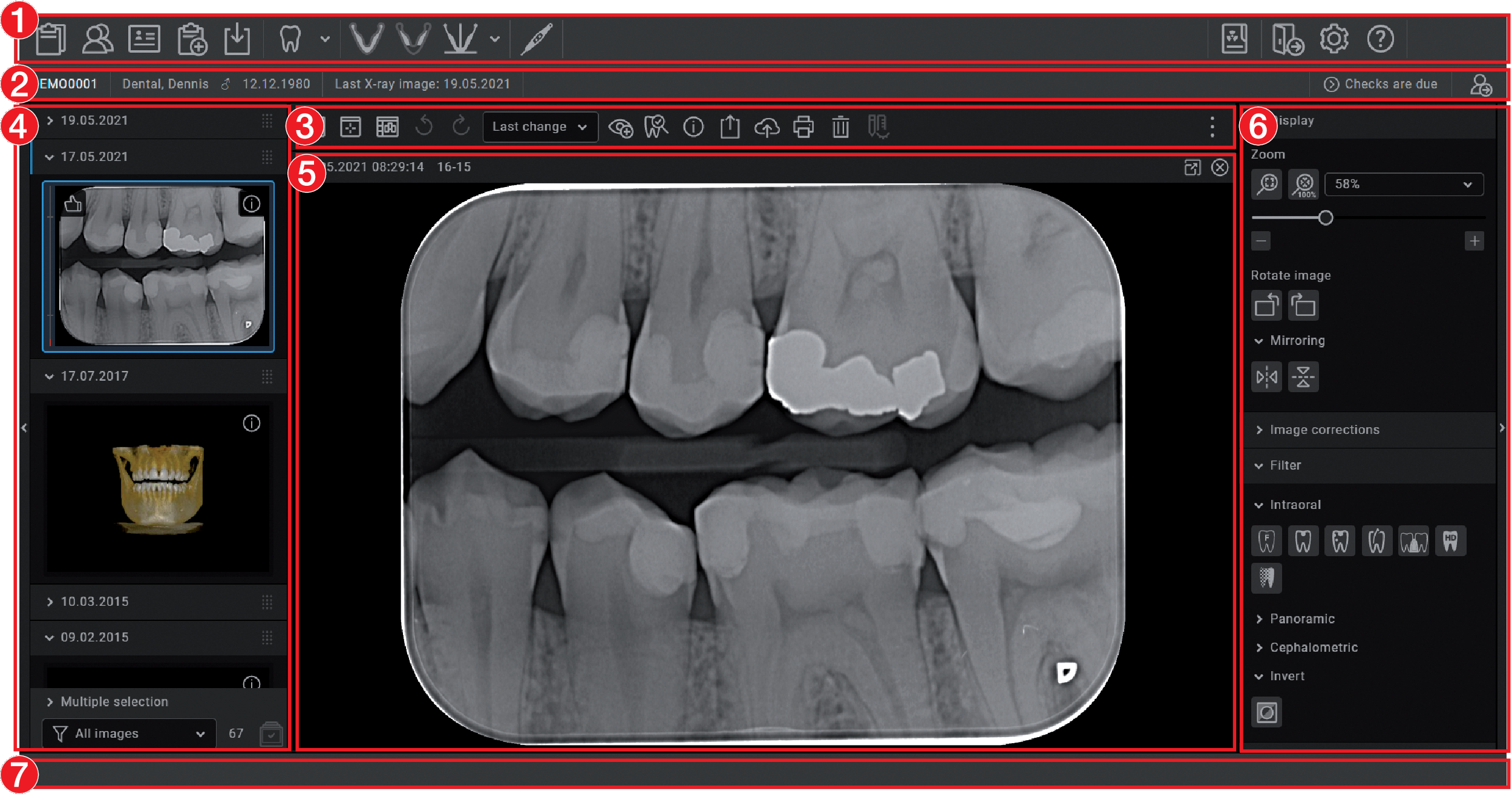
Menu bar
The menu bar is generally divided into two sections:
Left-hand section | |
|---|---|
  | Task administration (see Managing tasks) |
 | Display cloud cases (see Using VistaSoft Cloud |
  | Patient data management (see Managing patient data) |
 | Image import (see Importing images) |
    | X-ray image, by acquisition types, (see Acquiring images) |
 | Video acquisition (see Creating a video image with an intraoral camera) |
 | Create 3Shape case |
Right-hand section | ||
|---|---|---|
 | X-ray report (see Displaying the X-ray report) | |
 | Logging out a logged-in user and practice (see Change practice (surgery)) | |
| Configuration (see Configuration overview) | |
| Help | |
| Display help | |
 | Create support file (see Creating a support file) | |
 | Supported devices | |
| Show Info dialog | |
Patient data bar
- Left-hand section
- Information about the currently selected patient (see Managing patient data)
- Right-hand section
Information for the active task
Reminders if checks are due
Light table menu
The light-table menu features various commands for the images displayed on the light table:
 | |
  | |
  | Locking/unlocking the light table When free image arrangement is chosen, the position and size of the image frames on the light table can be locked (see Using a fixed/free image arrangement). |
 | |
 | |
 | Transferring images to the practice management software (only visible if the VDDS media interface is activated, see Interfaces) |
  | Repeat or undo actions |
 | Create user-defined image state (see Displaying and managing the image status) |
 | |
 | |
 | |
 | |
 | |
 | |
 | |
 | |
 | Open VistaSoft Trace to edit images for the logged in patient that have already been exported. |
 | |
 | |
 | |
  | |
 | |
  | |
 | Opens a selection list with further commands: |
 | |
 |
Image inspector
The "Image inspector" is divided into three sections:
Preview window:
can only be viewed if new images have been recorded
Image archive for the patient record you are logged into:
All images are grouped according to the date on which they were recorded.
Processing and filtering images from the image archive:
If the retention period required by law is activated (see Configuration), then X-ray images cannot be deleted until this period has expired.
In the preview window, you can open the troubleshooting via  if a device error occurs during image acquisition. Not all devices support this function. The scope of the troubleshooting options depends on the connected device.
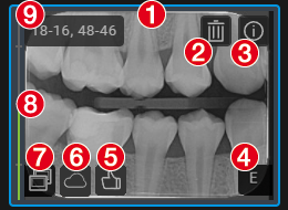
If it is available, the following information is displayed for each image in the Image archive:
- 1Blue frame, if the image is displayed on the light table
- 2Delete image from archive
- 3Display image information
- 4Evaluation of the automatic image plate quality check
- 5User's image evaluation
- 6Upload image to cloud
- 7Derived image (screenshot)
- 8Dose indicator
- 9Teeth shown
If corresponding information is available, the dose indicator is displayed next to each X-ray image as a colour bar. The dose indicator serves as a guide value for optimum adjustment of the dosage parameters. This shows whether there is a risk of under or over-exposing the image, i.e. whether low or high grey values can no longer be displayed, resulting in a loss of image information. If the dosage parameters are set to the correct values, this is indicated by a green bar – if not, this is indicated by a red bar. Borderline settings are indicated with a yellow bar.
Bar red and high | -> | Decrease X-ray dosage or amplification of the recording system |
Bar yellow and high | -> | Slightly decrease X-ray dosage or amplification of the recording system |
Green bar | -> | X-ray dosage and amplification of the recording system are OK |
Bar yellow and low | -> | Slightly increase X-ray dosage or amplification of recording system |
Bar red and low | -> | Slightly increase X-ray dosage or amplification of recording system |
- VistaPano S
- VistaPano S Ceph
- VistaVox S
- VistaVox S Ceph
- Video Images
Light table
All images selected in the "Image inspector" are displayed on the light table.
If you click on an image on the light table, a header appears with the image acquisition date and, if present in the image information, the X-ray parameters and the tooth. The header also includes buttons for the following actions:
 | Maximize image on light table |
 | Minimize image on light table |
 | Maximize image to full screen |
 | Close image |
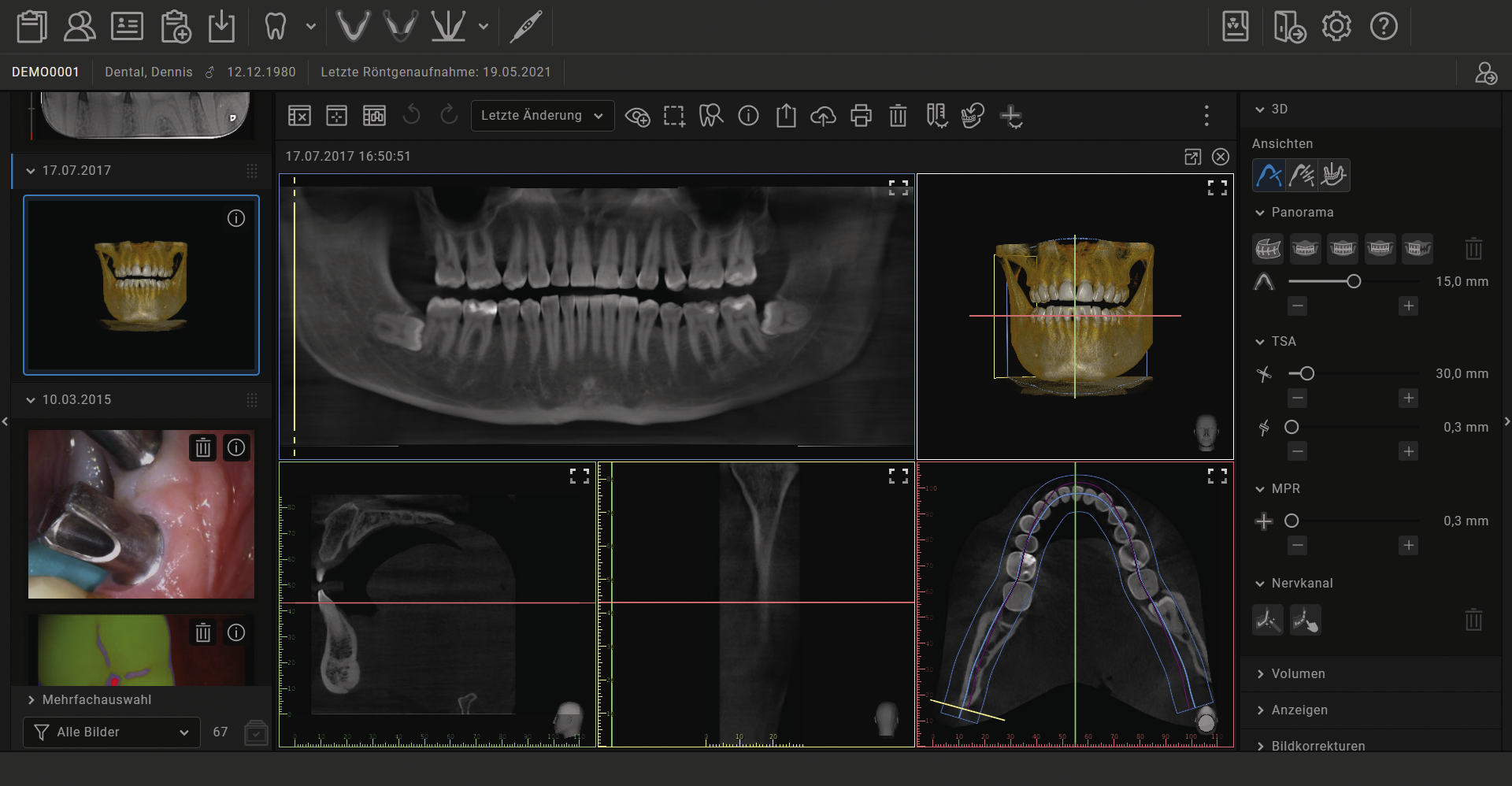
With CBCT images (3D) different views are shown (e.g. volume view, panorama view, axial slice, see 3D ). The views of the CBCT image can be individually maximised. The name of the view is then also displayed in the header (e.g. axial, sagittal).
To increase the size of the light table, the "Image inspector" (to the left) and the toolbox (to the right) can be collapsed. To do this, click on the side bar.
Toolbox
The toolbox contains the various tools and filters required for image editing (see Toolbox). The tools on offer differ depending on the image type.
Status bar
Status messages
Progress display
Notifications
Cloud connection
Pending PACS transfers
A new status message will pulse blue-grey for around 3 seconds. During image acquisition, device status messages are also displayed.
If activities are running in the background, clicking the progress bar of the status message will open a flyout in which all currently running activities are displayed.
General control elements
Flyouts
Flyouts open for various buttons (e.g. Patient, Configuration or Image Information) – as well as providing information, data can be entered or changed in these flyouts.
There are different ways to close the flyout again: by clicking on
or by clicking outside the flyout. The data that has been entered or changed will be automatically saved when a flyout is closed.
If a flyout has multiple levels a navigation bar will be displayed. This bar will allow you to switch directly to the higher levels.

If information is missing or invalid in a field, the field is outlined in orange and marked with
 . The inputs are checked when a flyout is closed or when you switch to a higher level of the flyout. If information is missing or values are invalid (e.g. outside a defined value range) then the flyout cannot be changed or you will not be able to switch to a higher level. You will either need to correct the inputs or discard the changes first.
Groupings of functions and images

- 1Function group View (closed)
- 2Function group Image corrections (open)
Images and functions are grouped in the "Image inspector" and in the toolbox. The groups can be opened or closed by clicking the group title.
Quick information
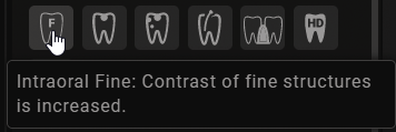
Quick information with a brief explanation is saved for the buttons on the software interface. If you briefly hover with the mouse cursor over a button the quick information will be displayed.
User support
When certain actions are performed or certain events occur, the imaging software will display a notification. This notification will appear as a flyout in the bottom right-hand corner. After around 5 seconds, the notification will automatically disappear. The type of notification is identified by the symbol denoting one of the following categories:
 | Error |
 | Warning |
 | Information |
In addition, a progress bar is shown in the status bar for actions that take a little time.
If a device error or warning occurs on the image acquisition device during the acquisition of images, a dialog window appears that needs to be confirmed. Device information appears as a message.
Notifications will only be displayed if there actually are any notifications. A notification counter (blue number) will also be displayed.
The notifications can still be retrieved from the system configuration after they have been deleted (see User notification ).
Starting the software
The following entries are present in the Windows Start menu after installation:
VistaSoft | |
Documentation | Opens the software manual |
DÜRR DENTAL SE | Opens the homepage of Dürr Dental |
e-Learning | Opens the e-Learning page on the Dürr Dental homepage |
Download remote maintenance | Starts the download of the TeamViewer software for remote maintenance by Dürr Dental |
Download pcvisit | Starts the download of the pcvisit software for remote maintenance |
ServerManager (only for single-station and server installations) | Launches the software for creating data backups |
Create file for Support | Creates a support file |
VistaSoft | Launches the imaging Software |
VistaSoft Inspect | |
VistaSoft Inspect | Launches the software for acceptance and consistency checks |
The following links are provided on the desktop:
 | VistaSoft |
 | VistaSoft Inspect |
 | e-Learning |
By clicking on the icon on the desktop
Via the Start menu: Start > All Programs > VistaSoft > VistaSoft
If the software is already running in the background, it can be opened.
CAUTION
Risk of data loss due to incorrect configuration
The configuration must only be performed by the manufacturer or by a person/body authorized by the manufacturer to do this.
- Create practice
- Adding devices
- Create an X-ray station (only required if there is an X-ray station obligation)
- Changing the display language
- Configuring image acquisition types
- Accelerating the image display for 3D images
- Create user
- Importing implant packages
- Dürr Dental Mobile Connect
- Configure VDDS-media interface to practice management program
- Configuring the DICOM/BDW interface
- Setting up the cloud
- Configuring features
Closing the software
If the main window of the software is closed, the software will continue to run in the background. This allows certain actions, e.g. tasks from VistaSoft Connect, to continue to be processed.
The software can be shut down in the taskbar.
Managing patient data
CAUTION
Personal injury is possible due to wrong assignment of image data to a patient
Check the right assignment of the image data (e. g. during image import, change of patient data new assignment of image data to a patient).
Observe the information displayed in the software.
Every image that is managed in the software is assigned to a patient.
To create or import new images, you must be logged into the record for the patient they relate to (see Searching for and logging into a patient record).
In the patient data management section, there are two ways of managing patient data:The patient data can be directly managed in the software itself (see Creating a patient record)
The patient data can be imported from the practice management software (see Importing patient data)
Creating a patient record
Once the software has been launched, the Patient Records flyout is automatically opened and a new patient record can be created.
in the menu bar.
 on the right-hand side of the search field.
Fields marked with
are mandatory fields and must be completed.
The mandatory fields can be selected in the configuration.
to close the flyout.
Importing patient data
Searching for and logging into a patient record
In order to create or import images, you must be logged into a patient record.
The Patient records flyout will open automatically when the software is launched.
If a patient is already logged in, you will automatically be logged out of this patient's record when you log into another patient's record. Here, all image acquisitions must be finished and all mandatory information for the images must have been entered.
The list Last patient logged in shows the last 10 patients who were logged in (with the most recent log-in date first). In the case of multi-station installations the list is global across all workstations. The list of last logged-in patients can also be deactivated, see Workstation .
The search values in the patient data can be limited to patient ID and name in the selection field. Otherwise, all fields of the patient data are used in the search.
.
 .
.
 , in the list below the search field (depends on the configuration, see
Practices
).
They can be sorted by clicking on the column head.
, in the list below the search field (depends on the configuration, see
Practices
).
They can be sorted by clicking on the column head. to log in.
Alternatively you can open the patient by double-clicking the list entry.
to log in.
Alternatively you can open the patient by double-clicking the list entry.Editing patient data
If the patient was imported from a practice management program via the VDDS-media interface or via patimport.txt, or via the DICOM interface, then it will not be possible to edit all the patient data.
.
Fields marked with
are mandatory fields and must be completed.
Different fields may be mandatory fields, depending on the configuration.
Log out patient
If the patient imaging is complete, you can log out from the patient's record.
When you log into another patient's record, you will automatically be logged out of the previous patient's record.
 in the patient data bar.
Importing X-ray images
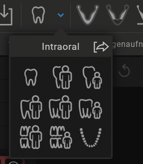
for the preferred intraoral image).
Via
 you can call up further acquisition types that belong to the grouping.
The imaging types in the favourites may differ depending the configuration (see
Acquisition types
).
you can call up further acquisition types that belong to the grouping.
The imaging types in the favourites may differ depending the configuration (see
Acquisition types
).
Depending on the configuration of the image types (see Acquisition types ) the software is either immediately ready for the X-ray acquisition, or you will first need to select the acquisition source and the image acquisition mode.
With VistaVox S/VistaVox S Cep and VistaPano S /VistaPano S Ceph, the X-ray parameters are automatically transferred from the device and cannot be altered.
 .
If the X-ray parameters have been entered or they are preselected in the configuration, the X-ray parameters are automatically adopted for the first imported image. If the preselected parameters are also to be applied to the other images, go to
Image information
for each image and click the button
Apply X-ray parameters
.
In addition, where applicable you should also select the tooth (multiple selection is possible) under
Dental notation system
and select the corresponding image acquisition type under
Image acquisition type
for which the image was created. By placing the marker in the dental notation system the image acquisition type is also automatically selected if it has not already been selected beforehand.
.
If the X-ray parameters have been entered or they are preselected in the configuration, the X-ray parameters are automatically adopted for the first imported image. If the preselected parameters are also to be applied to the other images, go to
Image information
for each image and click the button
Apply X-ray parameters
.
In addition, where applicable you should also select the tooth (multiple selection is possible) under
Dental notation system
and select the corresponding image acquisition type under
Image acquisition type
for which the image was created. By placing the marker in the dental notation system the image acquisition type is also automatically selected if it has not already been selected beforehand.
Creating a video image
A separate imaging window will open for video images. The imaging window is made up of the preview window and the image inspector.
If the camera is active, the live image from the camera can be seen in the preview window. If the camera is not active an animation is shown in the preview window.
Only the currently acquired images are displayed in the image inspector. When the imaging window is closed the images are transferred to the image archive of the patient.
in the menu bar.
to expand the video image to full screen if necessary.
 (see
Adjusting the video settings
).
(see
Adjusting the video settings
).
 prophylaxis view and caries view
 .
.
 .
or the prophylaxis view
.
If there is too much ambient light when an image proof is being recorded,
.
or the prophylaxis view
.
If there is too much ambient light when an image proof is being recorded,
 will be displayed. The caries filter cannot be used with this image.
.
(only the dentition type and the dental notation are available in the image inspector). The image information can be edited or an Indication can be entered later via the functions in the light table menu (see
Managing images
).
will be displayed. The caries filter cannot be used with this image.
.
(only the dentition type and the dental notation are available in the image inspector). The image information can be edited or an Indication can be entered later via the functions in the light table menu (see
Managing images
).
 to return to the video preview.
Creating a surface scan
Surface scans are created with the VistaImpress module. Once the surface scan has been created, it can be transferred to the image inspector.
In the VistaImpress module it is possible to create up to five surface scans for each case (upper jaw, lower jaw, bite block, upper jaw prescan, lower jaw prescan). The surface scans are transferred individually to the image inspector.
For details about operation refer to the installation and operating instructions of the intraoral scanner VistaImpress Easy.
 is active.
in the menu bar.
.
is active.
in the menu bar.
.
Display Images
 .
.
 to load the marked images to the light table.
orClick and hold your mouse button on one of the selected preview images in the "Image inspector" and then move it to the light table. (drag & drop)
to load the marked images to the light table.
orClick and hold your mouse button on one of the selected preview images in the "Image inspector" and then move it to the light table. (drag & drop) section will appear in the right-hand part of the date row. This shows that the date row can be moved.
Image editing
Mouse wheel: zoom in/zoom out image section
Right mouse button:
 Move image section
The images can be edited using the tools from the toolbox in order to highlight details and facilitate diagnosis. The editing tools available depend on the image type.
The following types of image editing are possible on an X-ray image (2D):The following types of image editing are possible on an CBCT image (3D):The following types of image editing are possible in a CBCT view (2D derived from 3D):The following types of image editing are possible on a video image:Filter (for proof images only)
Image corrections (not for proof images)
The changes to the image will be saved alongside the original image as the Last change. In the light table menu, you can use the selection list to display the Original and the Original image (original with pre-selected image processing steps). See also Displaying and managing the image status.
Export image
Various predefined image export modes and a user-defined export are available for image exporting. The predefined modes can be adapted (see Image export modes... ).
The following settings can be selected during the user-defined export (see also Image export modes... ):Destination type
File path
File name
Image state
2D/3D X-ray format or video format
Anonymization of the data
Embed viewer
The selected settings for the user-defined export are saved locally and can be reused during the next export.
The images can also be exported to a data carrier, see Creating a patient medium .
in the light table menu.
Configuration
CAUTION
Risk of data loss due to incorrect configuration
The configuration must only be performed by the manufacturer or by a person/body authorized by the manufacturer to do this.
- Create practice
- Adding devices
- Create an X-ray station (only required if there is an X-ray station obligation)
- Changing the display language
- Configuring image acquisition types
- Accelerating the image display for 3D images
- Create user
- Importing implant packages
- Dürr Dental Mobile Connect
- Configure VDDS-media interface to practice management program
- Configuring the DICOM/BDW interface
- Setting up the cloud
- Configuring features
Changing the display language
The imaging software supports many different languages. This can be changed in the configuration.
.
Accelerating the image display for 3D images
The image display can be accelerated for a smoother display of CBCT images (3D) (depending on the graphics card in the workstation).
The GPU-accelerated display can also be activated when a 3D image is first opened.
.
Practices
In the practice configuration you can create, configure and delete practices.
.
Create practice
You will need to create at least one practice before you can work with the imaging software. This query is displayed once, when you launch the software for the first time.
The practice will then appear in the list of practices.
Creating a further practice
If the workstation is used by multiple practices, these can be created and then easily changed afterwards (see Change practice (surgery) ).
or
Practices
.
Configuring the practice
Once you have created practices they can be configured. Configuration options include e.g. settings for the retention period for X-ray images or database settings.
Deleting a practice
It is generally possible to delete practices once they have been created.
A practice can only be deleted if the following requirements are met:No patient data present
No user logged into this practice
Practice is not the main practice of a user
At least one other practice remains in the system after deleting
User
The user management controls the access of different users to the software and to the image database. The user who creates an image is documented for every image. If multiple practices have been created, different access rights can be assigned to users for different practices.
The user management is optional. An administrator password can be assigned when the software is started for the first time. This initially creates a default user with administrator rights. Alternatively, the user management can also be deactivated. If this is the case no user login window appears when the software is started.
Deactivation of the user management is a requirement for using the minimal interface of VistaSoft Connect.
There are four different user roles with different access rights:
Administrator
Dentist
Radiographer
Standard
The following functions are restricted to certain user roles. All other functions are not restricted and can also be used by a default user.
Function | Administrator | Dentist | Radiographer |
|---|---|---|---|
Edit configuration | ● |
|
|
Start ServerManager | ● |
|
|
Perform acceptance test | ● |
|
|
Manage default image settings | ● | ● |
|
Delete patient | ● | ● |
|
Delete image
| ● | ● |
|
Change indication | ● | ● |
|
Image information – change image date and time | ● | ● | ● |
Start image acquisition | ● | ● | ● |
Perform consistency check | ● | ● | ● |
Import image | ● | ● | ● |
Reassign image | ● | ● | ●* |
Transfer image to PACS partner | ● | ● | ● |
*Authorisation can be deactivated,see Practices.
You can create, configure and delete users in the configuration.
.
The list of created users opens.
Create user
When the software is started for the first time, a default user (Admin) is automatically created with administrator rights.
Further users can be created.
The user management is optional. It is recommended for the following requirements:Documentation of the person who created the image
Administration of user rights, e.g. for deleting images
For multiple practices: different access rights for users for different practices
 .
.
The user appears in the list of users.
Do not forget that the automatically created default user (Admin) also needs to be protected with a password (see Edit user ).
Edit user
.
Deleting an operator
At least one user with administrator rights must be present for every practice.
Adding devices
All devices that are connected with the software are displayed in the list of devices.
The following conditions must be fulfilled in order to display the devices that are connected to the software in the list of devices:- Devices are connected to the network or to the workstation.
- Devices are switched on.
- The additional component for the corresponding device is installed (see Installing additional components).
The list of supported devices (additional components that have already been installed) can be queried under > Supported devices.
You can sort the list of devices by clicking in the corresponding column of the header row.
If a device is not yet fully configured and therefore cannot yet be used, then the row is marked with the icon .
If all of the requirements are met, then the devices can be displayed in the list of devices and configured. The connection to the software is established automatically.
.
Connecting devices
All connected devices appear automatically in the list of devices. If this is not the case you will need to add the device manually (see Manually adding a device).

The exact process for installation and configuration of a device is described in the assembly instructions and the instructions for use/installation of the device.
On TWAIN devices you first need to complete the device settings (see Device settings) to use the device and in order to be able to create an X-ray station.
The tick in the check box next to Connected shows that the device is connected to the software.
Manually adding a device
If a connected device is not displayed in the list of devices, then you will need to manually register it.
The system will search for the device in the network and then display it in the list of devices.
Installing additional components
If the additional component of a device was not installed at the same time during the initial installation process then you will need to reinstall this additional component afterwards.
To do this, proceed in the same way as for the initial installation (see Installing the software).
X-ray stations
If there is a legal requirement for the recording of X-ray data and under Configuration > Application the option X-ray stations is enabled then you will need to create X-ray stations.
If there is no X-ray station obligation and the option Manually create X-ray stations under Configuration > Application is disabled, then the X-ray station will be automatically created in the background when a device is created, and no further configuration is required.
X-ray emitter
Image acquisition device
Operator information
Here, e.g. an X-ray emitter can be combined with different image plate scanners or one image plate scanner can be combined with different X-ray emitters into multiple X-ray stations.
The X-ray station that is marked as the favourite in the list of X-ray stations is displayed first in the selection list when the X-ray image acquisition is started.
If an X-ray station is to be permanently assigned to an image type, this can set up in the configuration of the image type (see Configuring image acquisition types).
In the X-ray station configuration you can create, configure and delete X-ray stations.
.
Create an X-ray station
Creating an X-ray-station using the wizard
VistaPano S
VistaPano S Ceph
VistaVox S
VistaVox S Ceph
Creating an X-ray-station manually
All VistaScan devices
VistaRay
Cephalometric/panoramic devices without digital image receiver (e.g. with image plate)
TWAIN devices
If there is no legal requirement for the recording of X-ray data, the option Create X-ray stations manually can be deactivated in Configuration > Application. As a result, the X-ray station will be automatically created in the background when a device is created, and no further configuration is required (see Automatic creation of X-ray stations).
Creating an X-ray-station using the wizard
The X-ray station will be displayed in the list of X-ray stations.
The information about the X-ray emitter for the created X-ray station has been automatically generated. The X-ray station can be configured via Configure (see Configuring an X-ray station).
If an X-ray station already exists with this X-ray device the system will not overwrite the configuration of the X-ray station; instead, a further X-ray station will be created.
Creating an X-ray-station manually
or go to the navigation bar and click
X-ray stations
.
Automatic creation of X-ray stations
> Application > Configuration
disable the option
Manually create X-ray stations
.
> Devices
and click
Update
.
orIn the preview window of the image inspector go to
Select image acquisition source
and click
 .
.
Configuring an X-ray station
If the configuration of an X-ray station is changed, it may be necessary to perform a new full or partial acceptance test.
Create X-ray emitter...
If there is a mandatory X-ray station requirement, then an X-ray emitter must be assigned to every X-ray station.
Entering recommended values for X-ray parameters
Depending on the unit, you can enter recommended values for the X-ray parameters for each image acquisition type of an X-ray station. It makes the work easier if the X-ray images are always taken with the same values. The recommended values for the X-ray parameters are entered automatically for the first image, but can still be adjusted if required. Depending on the unit, should you have any further images of the same exposure, the X-ray parameters will need to be entered manually.
The recommended values are optional. Individual parameters can also be left empty.
If recommended values are entered they are displayed in the preview window in the recording mode.
It is not possible to enter recommended values in X-ray stations with VistaPano and VistaVox. With these units, the X-ray parameters are transferred directly.
Deleting an X-ray station
Acquisition types
The image acquisition types define the use of the acquisition source and the acquisition mode for the different X-ray images and video recordings (e.g. Intraoral, Video).
The list of image acquisition types is predefined based on the enabled software modules (e.g. Video, X-ray). The assignment of acquisition source and image acquisition mode can be configured (see Configuring image acquisition types).
The image acquisition types marked as Favourite appear as a button in the menu bar.
If the acquisition source and the image acquisition mode are fixed for an image acquisition type, the image acquisition will start immediately as soon as the image acquisition type is clicked in the menu bar.
The configuration of image acquisition types and the selection of favourites is always saved locally on the computer.
Configuring image acquisition types
The list of image acquisition types is predefined. For every image acquisition type you can set which acquisition source (image acquisition device) and which image acquisition mode are to be used to generate the image.
.
The configuration is active for the next image acquisition with this image acquisition type.
The option Restore default settings can be used to reset the configuration of an image acquisition mode.
Importing implant packages
Implant packages from various manufacturers can be downloaded in the download centre:

Implant models from different manufacturers can be imported. The implant models can be inserted in the images schematically (see Implants).
> Application.When performing a fresh import of the implant package of a manufacturer, the implant models are updated.
Implants stored in the software which are no longer available from a certain manufacturer are deleted. The previous use of these implants in the images is not changed.
Dürr Dental Mobile Connect
The software component Mobile Connect configures and connects the VistaSoft database with the Dürr Dental Imaging iPad app. The images saved in the VistaSoft database are transferred via Mobile Connect to the iPad and displayed. If various users or practices have been created in VistaSoft, they will also need to be logged into Mobile Connect.
For a multi-station installation it is sufficient to install Mobile Connect on one workstation.
When Mobile Connect is active
 is shown in the Windows taskbar.
To be able to use the Dürr Dental Imaging iPad app you will first need to enter the connection data in the iPad app.
.
 .
.
Configuring the interface to the practice management software
BDW and VDDS-media are available as interfaces to the practice management program.
Configuring the BDW interface to the practice management software
The interface BDW (BDW = Basic Dental Workflow) is an interface between the practice management software and the imaging software. It can be used to exchange patient data and image data between the practice management program and the imaging software. The practice management software can generate tasks, which can then be called up in the imaging software.
> Interfaces
.
> Practices
, enter the BDW practice ID.
> Interfaces
click
DICOM/BDW partner ... > Import BDW partner
.
Configure VDDS-media interface to practice management program
The VDDS-media interface (VDDS = Verband Deutscher Dentalsoftwareunternehmen, Association of German Dental Software Developers) is an interface between the practice management program and the imaging software. It can be used to exchange patient data and image data between the practice management program and the imaging software. The imaging software can be opened from within the practice management program.
The interface options depend on the practice management program used. The imaging software supports levels 1 to 6 of the VDDS interface.
> Interfaces
.
Configuring the DICOM/BDW interface
The meanings of the abbreviations used here are explained under Abbreviations used.
The configuration of the DICOM/BDW interface varies depending on the application.
Recall tasks from an RIS: | |
Return images to a PACS: | |
Print images on a DICOM printer: |
In the DICOM/BDW interface configuration, you can create, configure and delete the DICOM partner (RIS, PACS, printer).
.
Defining workstation as a DICOM workstation
In order to be able to use the DICOM functionality, at least one workstation has to be defined as a DICOM workstation.
Configuring the RIS connection
CAUTION
Personal injury is possible due to wrong assignment of image data to a patient
Check the right assignment of the image data (e. g. during image import, change of patient data new assignment of image data to a patient).
Observe the information displayed in the software.
If multiple RIS partners exist, a patient must possess the same unique patient ID for all RIS partners. Otherwise the same RIS partner would have be configured on each DICOM workstation.
Examples:- An existing RIS partner is replaced by a new RIS partner. The patients of the old RIS partner are stored in the imaging software. When the patients of the new RIS partner are imported, it is possible that different patients are assigned the same patient ID.
- DICOM workstations have different RIS partners. DICOM workstation A is linked to RIS partner A. DICOM workstation B is linked to RIS partner B. But both DICOM workstations share patient data through the imaging software. This means that different patients may have the same patient ID.
Creating an RIS partner
DICOM communication can only take place between known workstations (DICOM partners).
A list of all the created DICOM partners is displayed in the DICOM Partners... configuration.
Configuring the RIS query
Deleting RIS partners
Configuring the PACS connection
Creating a PACS partner
If multiple image states of a single image are to be transferred to the PACS, one PACS partner has to be created for each image state.
Deleting PACS partners
Configuring the DICOM printer
Creating the DICOM printer
Deleting the DICOM printer
Assigning DICOM attributes to certain acquisition types
The imaging software allows you to assign certain DICOM attributes to an acquisition type (for instance DICOM attribute IO to the acquisition type Intra). Depending on the configuration of the imaging software, this will cause acquisition to begin directly using the appropriate acquisition type.
If no appropriate assignment is found, or if no assignment has been made, the standard assignment will be used:
DICOM attribute | Meaning | Acquisition type |
|---|---|---|
No DICOM attribute present | Undefined | |
OT | Other type | |
CR | Computed Radiography | |
DX | Digital Radiography | |
DICOM attribute is not one of the attributes below | ||
IO | Intra-Oral X-ray | Intraoral |
XC | External Camera Photography | Video |
ES | Endoscopy | Video |
PX | Panoramic X-ray | Panoramic Standard |
CT | Computed Tomography | CBCT |
or
Interfaces
.
Delete assignment
The assignment of DICOM attributes to an acquisition type can be deleted.
.
Customising the task list
When working with DICOM tasks, you can configure which DICOM attributes are to be displayed in the task list.
List | The attribute is shown as a column in the task list |
Details | The attribute is shown in the DICOM area when a task is selected |
Hidden | The attribute will not be displayed |
Configuring features
Features contain special functions of the software as well as individually set up interfaces to external applications (third-party applications). The Feature settings are practice-specific.
.Setting up the cloud
The VistaSoft Cloud cannot be used in all countries.
Information on using the cloud is available under Using VistaSoft Cloud .
In the cloud configuration you can create a new cloud account, link an existing cloud account with the imaging software or remove an existing cloud link.
.
Create new cloud account
A cloud account must be created in order to use the VistaSoft Cloud.
If you already have a cloud account, you can simply link it to a practice in the imaging software (see Linking a practice with an existing cloud account ).
 icon in the status bar indicates that the imaging software has been linked with the cloud. If the link up failed, this will be indicated by the
 icon.
icon.
You will need to confirm your email address before using the cloud for the first time. For this purpose an email containing a confirmation link will be sent to the email address you entered.
In addition, you must accept the license agreement (EULA) when logging in for the first time. If the license agreement is changed, you need to accept the changes by entering your cloud password.
Linking a practice with an existing cloud account
If you already have a cloud account, you can simply link it to a practice in the imaging software.
icon in the status bar indicates that the imaging software has been linked with the cloud. If the link up failed, this will be indicated by the
icon.
Configuring the cloud account
After creating the cloud account you can configure it (e.g. by completing the profile or selecting a package)
> Features
.
Unlinking the cloud account
If the cloud is no longer needed the link can be removed.
> Features
.
VistaSoft Implant & Guide
The VistaSoft Implant & Guide software needs to be installed separately. You can download it in the Download Centre under www.duerrdental.com
A licence is required in order to use VistaSoft Implant & Guide (see Purchasing a licence for VistaSoft Implant & Guide ).
.
VistaSoft Trace
The VistaSoft Trace software needs to be installed separately. You can download it in the Download Centre under www.duerrdental.com
A licence is required in order to use VistaSoft Trace (see Licensing ).
.
3Shape integration
This feature can be used to link the imaging software with 3Shape TRIOS in Dental Desktop (3DD).
.The following button appears in the menu bar: .
Interface to third-party applications
This function is used to transfer images to an external application. The external application is started automatically and the image will be transferred. Whether or not the image will be loaded in the external application primarily depends on the functions available in the external application.
In the configuration, you can create, configure and delete external applications.
.
Add third-party application
or go to the navigation bar and click
Features
.
Settings for SICAT Implant
To connect to SICAT Implant, use the following settings:
External application name: | SICAT Implant |
Executable path: | C:\Program Files\SICAT\SICAT Suite\SicatSuite.exe |
Parameter: | -input "%PathToFile%" |
Image state: | Initial view |
Configuring a third-party application
or go to the navigation bar and click
Features
.
Deleting a third-party application
Operation
The section titled "Operation" explains how to operate the imaging software once you have got started (see First steps to find out how to get started).
Managing patient data
This section explains how to manage patient data.
CAUTION
Personal injury is possible due to wrong assignment of image data to a patient
Check the right assignment of the image data (e. g. during image import, change of patient data new assignment of image data to a patient).
Observe the information displayed in the software.
Creating a patient record
A patient can always be created unless an image acquisition is currently in progress.
Once the software has been launched, the Patient Records flyout is automatically opened and a new patient record can be created.
in the menu bar.
on the right-hand side of the search field.
Fields marked with
are mandatory fields and must be completed.
The mandatory fields can be selected in the configuration.
to close the flyout.
Importing patient data
The patient data can be imported individually from practice management program. If you are not logged into a patient record, you will automatically be logged into the patient's record when you import their data.
There are two ways to import patient data into the imaging software (see Interfaces):Import patient data with patimport.txt
Importing patient data via the VDDS media interface
Searching for and logging into a patient record
In order to create or import images, you must be logged into a patient record.
The Patient records flyout will open automatically when the software is launched.
If a patient is already logged in, you will automatically be logged out of this patient's record when you log into another patient's record. Here, all image acquisitions must be finished and all mandatory information for the images must have been entered.
The list Last patient logged in shows the last 10 patients who were logged in (with the most recent log-in date first). In the case of multi-station installations the list is global across all workstations. The list of last logged-in patients can also be deactivated, see Workstation .
The search values in the patient data can be limited to patient ID and name in the selection field. Otherwise, all fields of the patient data are used in the search.
.
.
, in the list below the search field (depends on the configuration, see
Configuration
).
They can be sorted by clicking on the column head.
to log in.
Alternatively you can open the patient by double-clicking the list entry.Editing patient data
If the patient was imported from a practice management program via the VDDS-media interface or via patimport.txt, or via the DICOM interface, then it will not be possible to edit all the patient data.
.
Fields marked with
are mandatory fields and must be completed.
Different fields may be mandatory fields, depending on the configuration.
Log out patient
If the patient imaging is complete, you can log out from the patient's record.
When you log into another patient's record, you will automatically be logged out of the previous patient's record.
in the patient data bar.
Delete patient
Provided certain requirements are met it is possible to delete a patient. When a patient's record is deleted, their images will be deleted with it.
.
.
The patient's record and all their images will be deleted.
Display Images
A preview of all of a patient's images will be displayed in the Image inspector. The images are grouped according to the date on which they were recorded.
To view or edit the images, they can be opened on the Light table.
Image inspector
The image inspector comprises the image archive with all of the images of the logged-in patient and the multiple selection and filter tools.
The images in the image archive are grouped according to the date on which they were recorded.
If new images are recorded, the preview window will also be displayed above the image archive.
The grading is displayed if the image quality has been graded in the image information:
 | Very good |
 | Acceptable |
 | Not acceptable |
For X-ray images acquired with an IQ image plate, the evaluation of the automatic image plate quality check (grade A to E) is displayed, see Automatic image plate quality check .
The following actions can be performed with the images in the image archive:Opening the image on the light table (see Display Images )
Opening, exporting, uploading to the cloud or deleting multiple images simultaneously (see Multiple selection )
Display Images
.
to load the marked images to the light table.
orClick and hold your mouse button on one of the selected preview images in the "Image inspector" and then move it to the light table. (drag & drop)
section will appear in the right-hand part of the date row. This shows that the date row can be moved.
Editing image information in the image inspector
Information on each of the images can be displayed and edited in the image inspector.
.
Multiple selection
One or more images can be edited using the "Image inspector's" multiple selection tool without the images being open on the light table.
next to the preview image for each image that is to undergo further processing using the multiple selection tool.
The check box can also be activated in the data bar. This selects all images recorded on the same day.
.
.
Do not include any patient data in the comment as this would compromise anonymity.
.
.
.
Filtering images
Over time, the dental practice and patient records will accumulate a large number of different images. The images can be filtered so that you can quickly find the images you require. The following filters can be applied:
All images | All images recorded for a particular patient will be displayed | |
 | Date range | All images recorded during the selected time frame will be displayed. |
 | Image types | All images of the selected image type for a particular patient will be displayed (multiple selection possible). |
 | No Indication | All images will be displayed for which no Indication is entered. |
| No findings | All images for which no diagnosis is entered will be displayed. |
 | Acquisition types | All images are displayed that were created with the selected image acquisition type (multiple selection possible). |
 | No tooth assignment | All images are displayed for which no tooth is selected in the dental notation system, as well as the images that have no dental notation system in their properties (e.g. Pano image). |
 | Dental notation | All images are displayed on which the filter selection matches the assigned teeth in the dental notation system. If several teeth are selected for the filtering, then all images are displayed that are assigned to at least one of these teeth. |
 | Image grading | All images with the selected image grading are displayed (multiple selection possible). |
The filters cannot be combined with each other.
Upon a change of the filter, the software remembers the settings (except to date range). If the filter is selected again, it is pre-set already.
 .
,
).
.
,
).
Light table
All images selected in the "Image inspector" are displayed on the light table.
If the VDDS-media interface is enabled, then the display of an image can also be triggered via the practice management program. Here, the corresponding patient is logged in via the imaging software and the image is opened on the light table.
Display Images
.
to load the marked images to the light table.
orClick and hold your mouse button on one of the selected preview images in the "Image inspector" and then move it to the light table. (drag & drop)
section will appear in the right-hand part of the date row. This shows that the date row can be moved.
Using a fixed/free image arrangement
If multiple images are displayed on the light table, different options are available for how the images are displayed.
| Fixed image arrangement (default setting): The image frames are arranged on the light table based on a fixed grid depending on the number of image frames. |
| Free image arrangement: The images can be freely positioned on the light table. The size of the image frames can be freely scaled. |
The last selected image arrangement mode is retained when the patient is changed or the software is closed and reopened.
to switch to the free image arrangement setting on the light table.
to switch to the fixed image arrangement setting on the light table.
Maximise image
If more than one image is open on the light table, these will be displayed next to and above and below one another. Each of these images can be maximised for a detailed view.
 .
Alternatively, you can also double-click the image to maximise it.
.
Alternatively, you can also double-click on the image to minimise it.
.
.
Alternatively, you can also double-click the image to maximise it.
.
Alternatively, you can also double-click on the image to minimise it.
.
Resizing views (only for CBCT)
The views of a CBCT image are opened in a default size. You can resize them as you wish to suit the particular application and your personal preferences. View sizes are not saved. When opened the next time, the CBCT image will again appear in the default size.


Enlarging and moving image details
The whole image is displayed when it is opened on the light table. To view details, the image can be magnified (zoom). The image detail displayed can be moved around within the frame.
Rotating the surface scan
The surface scan can be rotated around its centre point.
The current view is saved as image status Last Change and displayed as a preview image in the image inspector.
Editing image information on the light table
Information on each of the images can be displayed and edited on the light table.
Image information
in the light table menu (see
Light table menu
).
Close image
.
The image is removed from the light table. The editing of the image is saved. The current view is saved as image status Last Change and displayed as a preview image in the image inspector.
Clear lightbox
If there are too many images open on the light table, or if the light table needs to be cleared to make way for new images, you can make all the images disappear from the light table.
in the light table menu.
Views and layouts
With Views and layouts you can display multiple images from a patient in a certain layout on the light table. The views are saved for the patient.
Various predefined layouts are available for creating the views.
A layout defines the number, size and position of the frames on the light table. The pre-defined layouts can be edited, and additional layouts can be created. In the case of multi-station installations, the layouts are saved centrally and are available from all workstations.
Image properties can be assigned to the frames of a layout (image type, acquisition type, teeth). The image properties are shown in the empty frames of the layout.
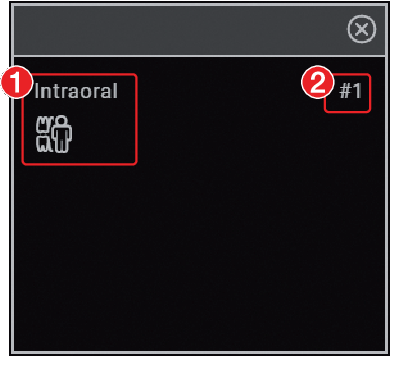
- 1Image properties of the frame (in this example: Image type = Intraoral, Acquisition type = Intraoral bite wing adult)
- 2Frame number
The frame numbers indicate the order in which the frames are filled. If an image series is started (see Creating an image series) then the newly created images are inserted directly in the order of the frames into the view.
If the option Fill frame with current images is activated, then when a new view is created the existing images are assigned to the frames with the corresponding image information.
Creating views
The views are created on the basis of layouts, which predefine the number, position and properties of the images by using frames.
The frames of a view can be filled with existing images from the image inspector or with newly created images (see also Creating an image series).
. .
.Clear the light table (
)Load a different or new view
Log out patient
Log out practice
Close the software
Managing views
Available views can be loaded on the light table, edited and deleted.
.
in the frame.
in the empty frame.
.
orLoad a different view or a new view.orLog out the patient or practice.orClose the software.
.
.
Creating a new empty layout
.

 ) is displayed, press the left mouse button and hold the button while dragging the edge of the frame to the required size.
 ) and drag the frame to the desired location, then release the mouse button. .
Creating a new layout on the basis of the current arrangement on the light table
.Editing layouts
. for the layout.
If the predefined layouts have been changed, these changes can be undone via Restore default layouts.
Creating a screenshot of the light table
If multiple images are open on the light table, it is possible to create a screenshot of the entire light table.
The screenshot contains all images as displayed on the light table (incl. comments), as well as empty frames if applicable. The image bars of the individual images are not included in the screenshot.
The screenshot is saved in the image inspector under the current date and is marked with  (derived image). It can be selected in the image inspector and opened / exported on the light table.
.Displaying and managing the image status
Depending on the image processing, certain image statuses are saved for every image. These can be called up for each image.
The following image statuses can be saved for the image:Last change : Last changes made to the image using the editing tools in the toolbox; this is automatically saved when the user switches to a different image state, when the image is removed from the light table or when the patient is logged out.
Initial view : Original image, configured image processing from the X-ray station has been applied (see Image processing )
Original : Image from the device including normalisation (e.g. inversion, mirroring)
Diagnosis : Image view saved with the diagnosis
User-defined image state : View is saved with date and time, can be deleted again.
.
.
next to the user-defined image state.
Creating a screenshot of the active image
You can create a screenshot of an image that is open on the light table.
The screenshot is saved in the image inspector directly under the original image and is marked with . It contains only the representation of the image that was shown on the light table at the time when the screenshot was taken. It is assigned the same acquisition date as the original image. The image information is also copied across.
The screenshot can be selected in the image inspector and opened on the light table.
.Display/hide annotations and measurements
Depending on whether or not annotations or measurements have been added to an image you can hide or show them.
The first click hides the added annotations and measurements. A second click shows them again.
.
.
Resetting all MPR and TSA planes
If the slice planes in a CBCT image have been changed, then they can be accurately restored to their axial, sagittal and coronal orientations. With panoramic views and TSA views the axial slice plane is restored to the plane on which the panoramic curve was originally defined.
.
Hide / show all MPR/TSA lines and the panorama curve
In CBCT recordings, working in the lightbox menus, the interfaces in the MPR and TSA slices and the Panorama view can be shown and hidden. The slice planes are always displayed in the volume view.
to fade in the lines.
to display the lines.
Managing images
The following different kinds of information can be saved for each image:
Image information (e.g. patient, dental notation system, image size, X-ray dose, device)
Diagnosis (indications, comments)
The image information can be displayed and edited.
Displaying and editing image information
The image information can be displayed via the "Image inspector" or the light-table menu.
The image information is split into different areas depending on the image type:
Dental notation | Assignment of the image to one or more teeth If the Tooth detection feature is activated (pre-selected), the visible teeth are automatically selected on intraoral images. The selection needs to be checked. With the dental notation The version of the dental notation system (FDI, UNS, Palmer) is defined in the configuration (see Dental notation). |
X-ray parameters | Properties of the X-ray image Depending on the image acquisition device, the values are entered manually or transferred by the unit. The X-ray parameters can be defined as mandatory fields (see Configuring the practice). Then they need to be filled in before a patient can be logged out or an image can be exported. |
Acquisition type | Information about the image acquisition mode and acquisition source of an X-ray image that are used The acquisition type is preselected based on the selection in the dental notation system. |
Image grading | The quality of an image can be graded as Very good, Acceptable or Not acceptable |
Findings | Documentation of the diagnosis Once the flyout has been closed the diagnosis can no longer be changed, but the comments can still be changed. A diagnosis view of the image is saved along with the diagnosis. |
Image details | Details about the image cannot be changed. |
The X-ray parameters can be changed as long as the patient is logged in and the image has not been exported. When you log out from the patient or export the image, the X-ray data is finally saved and can then no longer be changed.
In the case of images that were created with VistaPano, VistaVox or VistaImpress, the parameters entered by the device (e.g. X-ray parameters, acquisition type or restoration) cannot be changed.
in the light table menu or click the preview image in the image inspector. to close the flyout.
If the image has been matched to the wrong patient's record, it can be reassigned (see Assigning an image to a different patient record).
Entering the indication and diagnosis
A diagnosis, comprising indications, diagnostic findings and comments, can be added to each image.
A diagnosis view of the image is saved along with the diagnosis, and can be retrieved via the light table menu (see Light table menu ).
The entry in the field Diagnosis is saved with the user name and can no longer be changed once the flyout is closed.
The indication and comment can still be edited.
In the Diagnosis flyout, you can activate the option Automatically open this window for this image . In this way, when the image is opened on the light table, the Diagnosis flyout is always displayed as well. The setting applies only to this image and can be changed at any time.
or
.
Transferring an image to PACS
This function makes it simple to transfer images to a PACS. This requires the PACS to be configured (see Configuring the PACS connection ).
For images acquired without an active DICOM task (but with defined RIS partner and RIS query), the following options are available for transferring them to the PACS:Send images without task data to PACS
Send images later via the pending transfer list
Assign images to RIS task and send to PACS
Multiple images can be exported using the Multiple selection function in the image inspector (see Multiple selection ).
If the transfer to PACS is unsuccessful, the transfers will be saved in a list (see Pending transfers to PACS partner ).
in the light table menu.
in the light table menu.
in the light table menu.
CAUTION
Personal injury is possible due to wrong assignment of image data to a patient
Check the right assignment of the image data (e. g. during image import, change of patient data new assignment of image data to a patient).
Observe the information displayed in the software.
User-defined transfer to PACS partner
If you want to transfer images with different transfer settings to a configured PACS, you can use the function User-Defined Transfer to PACS Partner .
in the light table menu.
Pending transfers to PACS partner
If the images cannot be transferred to the PACS (e.g. due to failed connection to the network or server/PACS), they will be saved in a list. In addition, the Notifications flyout will appear.
 in the bottom right.
Transferring images to the practice management software
This function is only visible if the VDDS-media interface is activated (see Interfaces ).
If an image acquisition request is sent from the practice management software to the imaging software then the new images and changes to the image information of existing images can be sent to the practice software without logging out from the patient.
When you log out the patient or close the imaging software the new images and changes to the image information are automatically sent to the practice management program if the VDDS-media interface is enabled.
The
button is active if new images from a VDDS image acquisition request are present.
in the light table menu.
Assigning an image to a different patient record
If images have been saved under the wrong patient's record, they can be reassigned to the correct patient's record on the light table.
CAUTION
Personal injury is possible due to wrong assignment of image data to a patient
Check the right assignment of the image data (e. g. during image import, change of patient data new assignment of image data to a patient).
Observe the information displayed in the software.
and then
.
to select it.
Surface scans cannot be reassigned.
Delete image
If images are no longer required, they can be deleted.
Surface scans can only be deleted in the VistaImpress module, see Editing a surface scan.
In the image archive, the button is displayed on the image if the image can be deleted.
X-ray images recorded with the software cannot be deleted until the legally required retention period has passed (see Configuration).
on the image.orIf the image is open on the light table, go to the light table menu and click .Multiple selection
One or more images can be edited using the "Image inspector's" multiple selection tool without the images being open on the light table.
next to the preview image for each image that is to undergo further processing using the multiple selection tool.
The check box can also be activated in the data bar. This selects all images recorded on the same day.
.
.
Do not include any patient data in the comment as this would compromise anonymity.
.
.
.
Managing tasks
For every pending image acquisition you can create a task that can then be accepted and edited via the task overview at every workstation of a multi-station installation.
This allows the tasks to be processed at the workstation to which the corresponding image acquisition device is connected.
The tasks are listed in the task overview.
Displaying a task overview
All pending tasks (VistaSoft and DICOM) are listed in the task overview. If several practices have been created then only the tasks for the currently logged-in practice are visible. tasks that have been accepted at a different workstation are not displayed (this applies to VistaSoft tasks only - DICOM tasks remain visible). DICOM tasks are only displayed if the workstation has been defined as a DICOM workstation.
If BDW tasks from a different practice are present, the number of open tasks for the other practice is displayed at the end of the order overview. You can change practice by clicking this information.
The status of the tasks is indicated by means of an icon. A distinction is made between VistaSoft and DICOM tasks:
Imaging software task | DICOM task | Description |
|---|---|---|
 |  | New task |
 |  | task active |
 |  | task paused |
 |  | task completed |
 |  | Task cancelled |
The tasks can be sorted by column (e.g. date, image acquisition type).
In addition, the following filters are available (in the upper area click on Show options ):
Show favourites only: | If this is activated then tasks will only be displayed for the X-ray stations that have been marked as favourites for this workstation. |
Show completed and cancelled tasks: | If this option is not enabled then only tasks with the status New , Active (own workstation only) or Paused will be displayed. If enabled, tasks with the status Completed or Cancelled will also be displayed. |
The filter settings are saved separately for each each workstation.
task overview.
Create task
A new image acquisition task can be created in two ways depending on whether or not the patient is currently logged in.
It is only possible to create tasks within the imaging software. For DICOM tasks, the imaging software can only be used to process tasks but not to create them.
in the menu bar.
orIf the patient is not logged in: select the patient in patient management and click
.
in the task overview, see
Editing a task
.
If a workstation is linked in the X-ray station (see
Task management
), the task is automatically accepted and the recording unit is ready in standby.
Editing a task
in the menu bar.
 .
orDouble-click the task in the list.
.
orDouble-click the task in the list.The information about the active task can be called up in the patient data bar under Task information .
 in the patient data bar.
The task is interrupted. It can be continued from any workstation of a multi-station installation.
task overview.
in the patient data bar.
The task is interrupted. It can be continued from any workstation of a multi-station installation.
task overview.
The task can only be concluded if all mandatory information for the acquired images has been entered.
 in the patient data bar.
Cancel task
A task can only be cancelled if it has the status
Waiting
or
Paused
.
In the Tasks flyout, the cancelled tasks are also displayed if the option Show completed and cancelled tasks has been activated.
in the menu bar.
 .
.
Acquiring images
The imaging software allows the user to create or import X-ray and video images using the connected devices.
Before an X-ray image for a female patient can be started, a dialog window appears to check whether she is pregnant. This prompt will only be displayed once for as long as the female patient remains logged in.
The Pregnancy check can also be disabled, see Configuration. General responsibility for checking this lies with the dentist.
Importing X-ray images with VistaScan
for the preferred intraoral image).
Via
you can call up further acquisition types that belong to the grouping.
The imaging types in the favourites may differ depending the configuration (see
Configuration
).
Depending on the configuration of the image types (see Acquisition types ) the software is either immediately ready for the X-ray acquisition, or you will first need to select the acquisition source and the image acquisition mode.
For more information about this refer to the installation and operating instructions for the device.
in the image archive, enter X-ray parameters, see
Enter X-ray parameters/image information
.
Enter X-ray parameters/image information
If the X-ray parameters have not been entered or preselected in the configuration (see
Entering recommended values for X-ray parameters
) and the function
X-ray parameters mandatory
is activated (see
Practices
), then the X-ray parameters will need to be entered separately for each image under
.
If the X-ray parameters have been entered or they are preselected in the configuration, the X-ray parameters are automatically adopted for the first imported image. These values can also be adopted for the other images.
All fields marked
are mandatory fields and must be completed.
.
to close the flyout.
Creating an X-ray image with VistaScan in the SmartScan workflow
Using the VistaScan Smart Reader you can directly assign Image Plates IQ to a patient. The images are then automatically assigned to this patient when they are scanned.
A SmartScan-capable image plate scanner is required for scanning (see the device's installation and operating instructions).
Assignment of the image plate to a patient remains in place for a maximum of 8 hours and is deleted as soon as the image is scanned and assigned to the patient.
The status of the Smart Reader is shown via the status LED, see Status LED Smart Reader
is present in the menu bar. in the menu bar. . , ascending audio signal is heard
  (if configured).Multiple image plates can also be assigned to the patient. The dialog window shows the number of image plates that are currently assigned to the patient.
For more information about this refer to the installation and operating instructions for the device.
in the image archive, enter X-ray parameters, see Enter X-ray parameters/image information.Assign unassigned images
If image plates were scanned in the SmartScan workflow that are not assigned to a patient, an additional button
 appears in the menu bar. The number of unassigned images is indicated in orange.
.
Checking the generated X-ray station
If an X-ray station has not yet been created with the X-ray emitter used and the image acquisition device, a new X-ray station is generated when the image is scanned.
A warning symbol
appears on the light table for the image created with the generated X-ray station.
This X-ray station must be checked and approved.
Deleting the assignment of the image plate
The assignment of the image plates to one patient or to all patients of a practice can be deleted. In the process, all the patient information associated with the image plate will be lost.
This function is only visible for the user roles X-ray Assistant, Dentist and Administrator.
.
If the image plate already contains an X-ray image, this can still be read – see Assign unassigned images or Importing X-ray images with VistaScan.
Status LED Smart Reader
The following status notifications can be displayed via the status LED of the Smart Reader. In addition, audible signals can also be activated in the configuration, see Workstation.
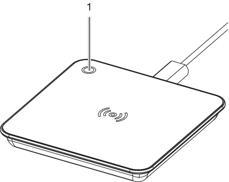
- 1Status LED
Status LED |
| Sound signal | Meaning |
|---|---|---|---|
 | Blue | Connected to computer | |
| Green | Ready – expecting an image plate for scanning | |
| Green | (2 rising notes) | Image plate detected and assigned to the patient |
  | Briefly orange, then yellow |  (2 identical tones) | Image plate has already been assigned to another patient
|
| Green |  (2x 2 rising notes) | Image plate has been successfully assigned to another patient |
 | Pink | An error has occurred.
|
Creating an X-ray image with VistaPano
The image can only be taken with the reconstruction PC that is directly connected to the image acquisition device. After the image has been saved in the database, the image can be viewed and edited at all workstations.
for a standard panoramic image).Via you can call up further acquisition types that belong to the grouping.Depending on how the image acquisition types are configured, the acquisition of the X-ray image will start either immediately or you will first need to select an X-ray station.
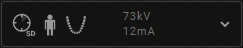
The status or progress of the image is shown in the preview window.
The image is automatically saved.
For information about operating the X-ray image acquisition device refer to the operating instructions of the device.
Parameter overview
Image quality
 | HD panoramic images An improved signal/noise ratio is achieved via an extended exposure time. |
 | SD panoramic images This setting is used for standard images. |
Patient type
Selection of patient type will depend on the patient's size or their head circumference. This means that the preset patient type may need to be changed if necessary.
The X-ray parameters are preset using the patient type.
If a child is selected then the x-ray parameters are different:
- Reduced dose
- Shorter circulation time
- Smaller radiation field
 | large, large build patient |
 | normal, average build patient |
 | small, small build patient or adolescent |
 | child (< 12 years) |
Arch
The selected jaw form influences the rotational behaviour of the C-shaped angle connector piece during image acquisition. This enables an image with an ideal layer position to be captured even on a particularly narrow or wide jaw.
 | Normal arch |
 | Narrow arch |
 | Wide arch |
 | Child arch |
Imaging program, adult
The selection of the imaging programs depends on the image acquisition device.
For panoramic images of children, the size of the radiation field is reduced with the aid of an additional collimator. The radiation dose is significantly reduced for this image.
Panoramic images | ||
|---|---|---|
 |  | Standard The standard panoramic image records the complete dental area with ascending dental branches and maxillary joints. |
 |  | Front The image shows a reduced dental area without ascending dental branches. |
 |  | Right The image only shows the right dental area. |
 |  | Left The image only shows the left dental area. |
 | 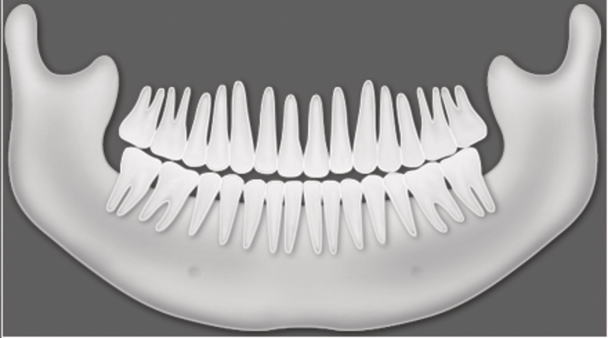 | Orthogonal The image shows the complete dental area and is generated perpendicular to the maxillary arch. This prevents overlapping crowns. |
 | 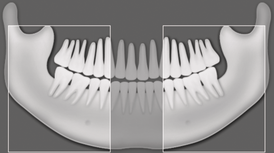 | Bitewing The image shows the lateral dental area with a size limited to the bite wings. |
 | 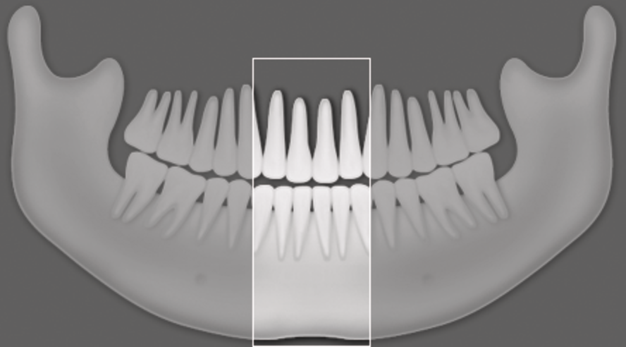 | Bite wing front The image shows the anterior area with a size limited to the bite wings. |
 | 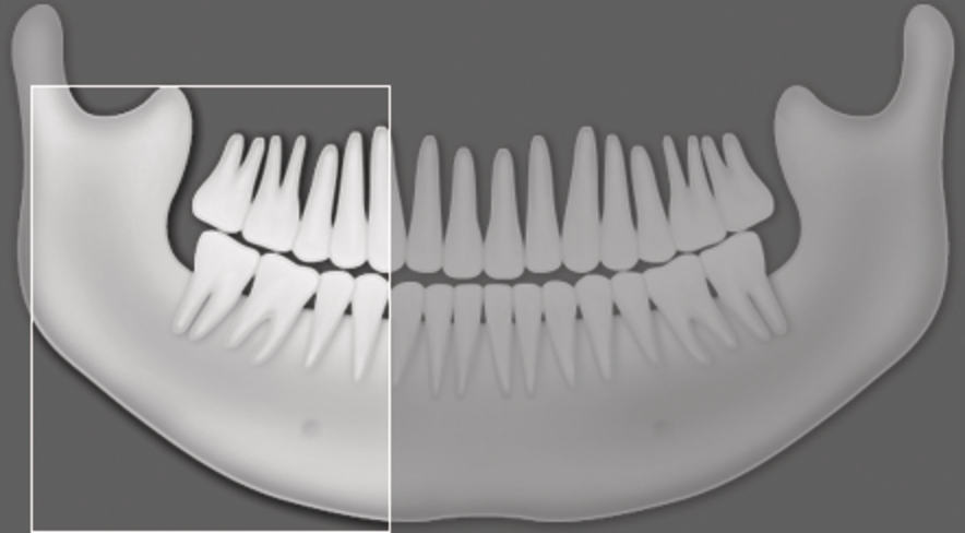 | Bite wing right The image shows the right posterior region with a size limited to the bite wings. |
 |  | Bite wing left The image shows the left posterior region with a size limited to the bite wings. |
Temporomandibular imaging | ||
|---|---|---|
 |  | Maxillary joint, lateral The image shows the lateral maxillary joints with an open and closed mouth in 4-fold depiction on one image. |
 |  | Maxillary joint, PA The image shows the posterior-anterior maxillary joints with an open and closed mouth in 4-fold depiction on one image. |
Sinus images | ||
|---|---|---|
 |  | Sinus, lateral The image shows the lateral sinuses. |
 |  | Sinus, PA The image shows the posterior-anterior sinuses. |
Cephalometric exposures | ||
|---|---|---|
 |  | Head lateral full format The X-ray image shows the patient's complete skull from the side. This X-ray program can be selected dependent on the version. |
 |  | Head lateral The X-ray image shows the patient's cranium from the side. This X-ray program can be selected dependent on the version. |
 |  | Head PA The image shows the posterior/anterior cranium. It is suitable for semi-axial cranial images and provides a cranial eccentric overview. |
 |  | SMV The image shows the cranium in a submentovertex projection. It is suitable for recording the maxillary arch and the maxillary joints, for example. |
 |  | Waters View This view is suitable for recording the articular head in the mandibular joint socket, for example. |
 |  | Carpus The image shows the carpus of the patient. It is suitable for providing conclusions on the growth stage of the body/jaw. |
Imaging program, child
For panoramic images of children, the size of the radiation field is reduced with the aid of an additional collimator. The radiation dose is significantly reduced for this image.
Panoramic images | ||
|---|---|---|
|  | Standard The standard panoramic image records the complete dental area with ascending dental branches and maxillary joints. |
| 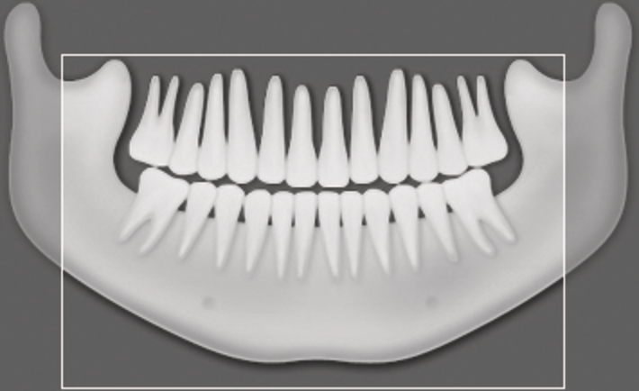 | Front The image shows a reduced dental area without ascending dental branches. |
| 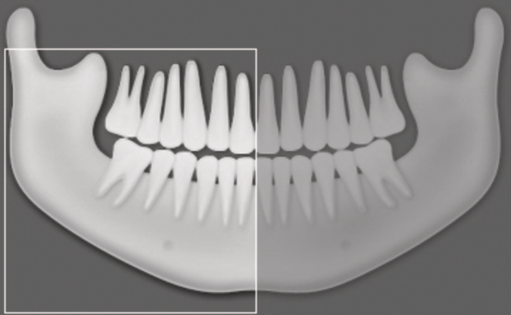 | Right The image only shows the right dental area. |
| 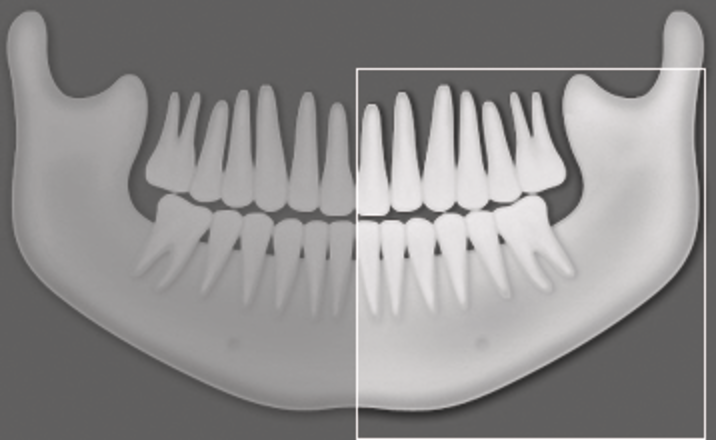 | Left The image only shows the left dental area. |
Taking an X-ray image with VistaVox
The image can only be taken with the reconstruction PC that is directly connected to the image acquisition device. After the image has been saved in the database, the image can be viewed and edited at all workstations.
for a CBCT image).
Via
you can call up further acquisition types that belong to the grouping e.g.
 for 5x5 maxilla molar right (see
Acquisition types
).
for 5x5 maxilla molar right (see
Acquisition types
).
Depending on how the image acquisition types are configured, the acquisition of the X-ray image will start either immediately or you will first need to select an X-ray station.
The status or progress of the image is shown in the preview window.
For information about operating the X-ray image acquisition device refer to the operating instructions of the device.
The image is automatically saved.
The preview window is closed. All acquired images are transferred to the image archive of the logged on patient. The newest images appear at the top of the image archive. From there, the images can then be opened on the light table and edited (see Editing images). Similarly, indications can be entered via the functions in the light table menu, or the image information can be edited (see Managing images).
Parameter overview
Acquisition types
The selection of the imaging programs depends on the image acquisition device.
CBCT images | |
|---|---|
 | CBCT The CBCT image shows the jaw area. The size of the jaw area shown depends on the selected image volume. Resolution: 200 μm |
 | CBCT upper jaw The X-ray image shows the upper jaw. Resolution: 200 μm |
 | CBCT lower jaw The X-ray image shows the lower jaw. Resolution: 200 μm |
| CBCT 5x5 Maxilla Molar right The X-ray image depicts the right molar region of the maxilla with a volume of 5x5 cm. Resolution*: 120 μm |
 | CBCT 5x5 Maxilla Premolar right The X-ray image depicts the right premolar region of the maxilla with a volume of 5x5 cm. Resolution*: 120 μm |
 | CBCT 5x5 Maxilla Front The X-ray image depicts the front region of the maxilla with a volume of 5x5 cm. Resolution*: 120 μm |
 | CBCT 5x5 Maxilla Premolar left The X-ray image depicts the left premolar region of the maxilla with a volume of 5x5 cm. Resolution*: 120 μm |
 | CBCT 5x5 Maxilla Molar left The X-ray image depicts the left molar region of the maxilla with a volume of 5x5 cm. Resolution*: 120 μm |
 | CBCT 5x5 Mandible Molar right The X-ray image depicts the right molar region of the mandible with a volume of 5x5 cm. Resolution*: 120 μm |
 | CBCT 5x5 Mandible Premolar right The X-ray image depicts the right premolar region of the mandible with a volume of 5x5 cm. Resolution*: 120 μm |
 | CBCT 5x5 Mandible Front The X-ray image depicts the front region of the mandible with a volume of 5x5 cm. Resolution*: 120 μm |
 | CBCT 5x5 Mandible Premolar left The X-ray image depicts the left premolar region of the mandible with a volume of 5x5 cm. Resolution*: 120 μm |
 | CBCT 5x5 Mandible Molar left The X-ray image depicts the left molar region of the mandible with a volume of 5x5 cm. Resolution*: 120 μm |
* The resolution can be changed to 80 μm in the service menu of the unit.
For panoramic images of children, the size of the radiation field is reduced with the aid of an additional collimator. The radiation dose is significantly reduced for this image.
Panoramic images | ||
|---|---|---|
| | Standard The standard panoramic image records the complete dental area with ascending dental branches and maxillary joints. |
| | Front The image shows a reduced dental area without ascending dental branches. |
| | Right The image only shows the right dental area. |
| | Left The image only shows the left dental area. |
| | Orthogonal The image shows the complete dental area and is generated perpendicular to the maxillary arch. This prevents overlapping crowns. |
| | Bitewing The image shows the lateral dental area with a size limited to the bite wings. |
| | Bite wing front The image shows the anterior area with a size limited to the bite wings. |
| | Bite wing right The image shows the right posterior region with a size limited to the bite wings. |
| | Bite wing left The image shows the left posterior region with a size limited to the bite wings. |
Temporomandibular imaging | ||
|---|---|---|
| | Maxillary joint, lateral The image shows the lateral maxillary joints with an open and closed mouth in 4-fold depiction on one image. |
| | Maxillary joint, PA The image shows the posterior-anterior maxillary joints with an open and closed mouth in 4-fold depiction on one image. |
Sinus images | ||
|---|---|---|
| | Sinus, lateral The image shows the lateral sinuses. |
| | Sinus, PA The image shows the posterior-anterior sinuses. |
Cephalometric exposures | ||
|---|---|---|
| | Head lateral full format The X-ray image shows the patient's complete skull from the side. This X-ray program can be selected dependent on the version. |
| | Head lateral The X-ray image shows the patient's cranium from the side. This X-ray program can be selected dependent on the version. |
| | Head PA The image shows the posterior/anterior cranium. It is suitable for semi-axial cranial images and provides a cranial eccentric overview. |
| | SMV The image shows the cranium in a submentovertex projection. It is suitable for recording the maxillary arch and the maxillary joints, for example. |
| | Waters View This view is suitable for recording the articular head in the mandibular joint socket, for example. |
| | Carpus The image shows the carpus of the patient. It is suitable for providing conclusions on the growth stage of the body/jaw. |
Image acquisition volume
The selection of the imaging volume will depend on the patient's size or their head circumference.
 | Standard imaging volume for adults The image acquisition covers a cylindrical region (diameter approx. 10 cm, height approx. 8.5 cm). |
 | Smaller imaging volume for children The image acquisition covers a cylindrical region (diameter approx. 10 cm, height approx. 7 cm). |
Image quality
 | An improved signal/noise ratio is achieved via an extended exposure time and a higher dosage. |
 | This setting is used for standard images. |
Patient shape
Selection of patient type will depend on the patient's size or their head circumference. This means that the preset patient type may need to be changed if necessary.
The X-ray parameters are preset using the patient type.
If a child is selected then the x-ray parameters are different:
- Reduced dose
- Shorter circulation time
- Smaller radiation field
| large, large build patient |
| normal, average build patient |
| small, small build patient or adolescent |
| child (< 12 years) |
Arch
The selected jaw form influences the rotational behaviour of the C-shaped angle connector piece during image acquisition. This enables an image with an ideal layer position to be captured even on a particularly narrow or wide jaw.
| Normal arch |
| Narrow arch |
| Wide arch |
| Child arch |
Taking an X-ray with VistaRay
Every VistaRay sensor requires individual calibration data. This data is enclosed with the sensor on a calibration data carrier and needs to be installed for each sensor.
for the preferred intraoral image).
Via
you can call up further acquisition types that belong to the grouping.
The imaging types in the favourites may differ depending the configuration (see
Configuration
).
Depending on the configuration of the image types (see Acquisition types ) the software is either immediately ready for the X-ray acquisition, or you will first need to select the acquisition source and the image acquisition mode.
For more information about this refer to the installation and operating instructions for the device.
.
If the X-ray parameters have been entered or they are preselected in the configuration, the X-ray parameters are automatically adopted for the first imported image. If the preselected parameters are also to be applied to the other images, go to
Image information
for each image and click the button
Apply values
.
In addition, where applicable you should also select the tooth (multiple selection is possible) under
Dental notation system
and select the corresponding image acquisition type under
Image acquisition type
for which the image was created. By placing the marker in the dental notation system the image acquisition type is also automatically selected if it has not already been selected beforehand.
Taking an X-ray image with a TWAIN device
for the preferred intraoral image).
Via
you can call up further acquisition types that belong to the grouping.
The imaging types in the favourites may differ depending the configuration (see
Configuration
).
Depending on the configuration of the image types (see Acquisition types ) the software is either immediately ready for the X-ray acquisition, or you will first need to select the acquisition source and the image acquisition mode.
For more information about this refer to the installation and operating instructions for the device.
>
 in the preview window.
.
If the X-ray parameters have been entered or they have been preselected in the configuration, the X-ray parameters are automatically adopted for the first imported image. If the preselected parameters are also to be applied to the other images, go to
Image information
for each image and click the button
Apply values
.
In addition, where applicable you should also select the tooth (multiple selection is possible) under
Dental notation system
and select the corresponding image acquisition type under
Image acquisition type
for which the image was created. By placing the marker in the dental notation system the image acquisition type is also automatically selected if it has not already been selected beforehand.
in the preview window.
.
If the X-ray parameters have been entered or they have been preselected in the configuration, the X-ray parameters are automatically adopted for the first imported image. If the preselected parameters are also to be applied to the other images, go to
Image information
for each image and click the button
Apply values
.
In addition, where applicable you should also select the tooth (multiple selection is possible) under
Dental notation system
and select the corresponding image acquisition type under
Image acquisition type
for which the image was created. By placing the marker in the dental notation system the image acquisition type is also automatically selected if it has not already been selected beforehand.
Creating a video image with an intraoral camera
A separate imaging window will open for video images. The imaging window is made up of the preview window and the image inspector.
If the camera is active, the live image from the camera can be seen in the preview window. If the camera is not active an animation is shown in the preview window.
Only the currently acquired images are displayed in the image inspector. When the imaging window is closed the images are transferred to the image archive of the patient.
in the menu bar.
to expand the video image to full screen if necessary.
(see
Adjusting the video settings
).
prophylaxis view and caries view
.
.
or the prophylaxis view
.
If there is too much ambient light when an image proof is being recorded,
will be displayed. The caries filter cannot be used with this image.
.
(only the dentition type and the dental notation are available in the image inspector). The image information can be edited or an Indication can be entered later via the functions in the light table menu (see
Light table
).
to return to the video preview.
Adjusting the video settings
Depending on the camera used the video settings can be adjusted in the preview window.
 | Brightness | Adjust the brightness of the preview image with the slider |
 | Contrast | Adjust the contrast of the preview image with the slider |
 | Saturation | Adjust the saturation of the preview image with the slider |
 | Sharpness | Adjust the sharpness of the preview image with the slider |
 | Gamma | Adjust the gamma value of the preview image with the slider |
 | Resolution | Adjust the resolution of the preview image |
The video settings are reset to the standard values with Reset .
Creating video images with a TWAIN device
A separate imaging window will open for video images. The imaging window is made up of the preview window and the image inspector.
In addition, the software of the TWAIN device also opens.
The TWAIN logo is displayed in the preview window.
Only the currently acquired images are displayed in the image inspector. When the imaging window is closed the images are transferred to the image archive of the patient.
in the menu bar.
.
(only the dentition type and the dental notation are available in the image inspector). The image information can be edited or an Indication can be entered later via the functions in the light table menu (see
Displaying and editing image information
).
Creating an image series
An image series is used to combine the newly acquired X-ray or video images directly in a view.
The view can be reopened at any time, see Creating views.
The existing layouts and views can be managed via the light table menu, see Views and layouts.
in the light table menu.If required, it is also possible to activate a different frame (e.g. #3). Afterwards the next free frame will then be free (e.g. #4).
 . and remove it from the view. .
Creating a surface scan
Surface scans are created with the VistaImpress module. Once the surface scan has been created, it can be transferred to the image inspector.
In the VistaImpress module it is possible to create up to five surface scans for each case (upper jaw, lower jaw, bite block, upper jaw prescan, lower jaw prescan). The surface scans are transferred individually to the image inspector.
For details about operation refer to the installation and operating instructions of the intraoral scanner VistaImpress Easy.
is active.
in the menu bar.
.
Importing images
- Importing image data via drag & drop
- Importing image files (single image import)
- Importing an image from the image cache (cache image import)
- Importing the DICOMDIR directory (DICOMDIR import)
- Importing an image from the device memory (standalone / retrieve)
- Importing CBCT series (DICOM series import)
Patient metadata can be saved along with the image, allowing the image to be saved under a new patient record or allowing it to be matched to the relevant patient record that already exists. In addition, the image can also be matched to an existing patient record.
Depending on the information saved with the image, the image may be matched to an existing patient record, or new patient record can also be created.
The following file formats can be imported:DICOM (*.dcm)
PNG (*.png)
TIFF (*.tif, *.tiff)
JPEG (*.jpg)
JPEG 2000 (*.jp2, *j2k)
Bitmap (*.bmp)
XTF (original image state) (*.xtf)
VTF (*.vtf)
XYZ (*.xyz)
In addition, a DICOM series, i.e. a directory with individual layer images, can be imported. However, the DICOM series must have been taken with a Dürr Dental X-ray unit.
Importing image data via drag & drop
Individual images or directories can be imported via drag & drop.
Importing image files (single image import)
in the menu bar.
 .
.
Importing CBCT series (DICOM series import)
CBCT images that are available as a series of DICOM files (CT Image Storage or Enhanced CT Image Storage) can be imported (layers stored individually in a directory).
CBCT images that are available as a single DICOM file (just one file with the ending .dcm), can be imported with
(see
Importing image files (single image import)
).
in the menu bar.
.
Importing the DICOMDIR directory (DICOMDIR import)
in the ribbon. .
.Importing an image from the device memory (standalone / retrieve)
in the ribbon.
 .
.
Importing an image from the image cache (cache image import)
If it is not possible to transfer an image to the server after it is created, then it is saved in the image cache of the workstation (see Image cache ).
The import from the image cache can then be manually triggered from the workstation.
in the ribbon.
 .
.
Exporting images
Export image
Various predefined image export modes and a user-defined export are available for image exporting. The predefined modes can be adapted (see Image export modes... ).
The following settings can be selected during the user-defined export (see also Image export modes... ):Destination type
File path
File name
Image state
2D/3D X-ray format or video format
Anonymization of the data
Embed viewer
The selected settings for the user-defined export are saved locally and can be reused during the next export.
The images can also be exported to a data carrier, see Creating a patient medium .
in the light table menu.
Creating a patient medium
If the computer has a CD/DVD burner then you can burn individual images or multiple images for a patient onto a data carrier (CD or DVD). In addition to the images, it is also possible to burn a link to the viewing software (web application) onto the data carrier (see Image export modes...).
> Patient medium. > Patient medium.Exporting an image to an external application
This function is used to transfer any image to an external application. The image is saved to a temporary folder. When the external application is launched the image is automatically loaded to the external application.
in the light table menu.
Exporting an image to VistaSoft Trace
This function can be used to transmit a panoramic X-ray image or a cephalometric X-ray image with patient information to VistaSoft Trace.
in the light table menu.
.
Exporting an image to VistaSoft Implant & Guide
This function is used to transmit an image to VistaSoft Implant & Guide.
in the light table menu.
Editing images
The images can be edited on the light table (see Toolbox).
In addition, default image settings can be saved for each X-ray station, so that every time a new image is recorded, it is automatically displayed on the light table with these settings (see Managing default image settings).
Toolbox
The toolbox contains tools for editing the images on the light table.
The tools are divided into groups and can be expanded or collapsed by clicking

The selection of tools depends on the image selected on the light table.
Once it has been edited, the image is saved with the preview in the "Image inspector" as soon as another image is selected on the light table or the image is cleared from the light table.
The changes to the image will be saved alongside the original image. The original image ( Original image ) can be displayed again by clicking on the selection list in the light table menu.
3D
In cone beam computed tomography (CBCT), three-dimensional volume data is reconstructed from a large number of individual two-dimensional X-ray images. These 3D renderings are used for display purposes only and can be viewed and evaluated in different views and slices.
There are three different views (see Navigating in CBCT images (3D)) based on multiplanar reconstruction (MPR). Alongside the volume view, the MPR view shows three slices: the axial, sagittal and coronal slices. These slices can be individually modified.
In the panoramic view the axial and sagittal slice are shown, as well as the panoramic view (similar to a 2D panoramic X-ray image) and a transversal layer image (TSA).
With the TSA view, the axial slice, the pano view and also several transversal layer images are displayed. The number of TSA views can be adjusted.
Navigating in CBCT images (3D)
Various functions can be used to navigate through the slice planes/layers in the CBCT images. With the aid of these functions the slice planes can be moved or rotated in such a way that the important regions can be made visible for the examination.
In the illustration below all of the navigation functions have been made visible. Depending on the view (panoramic, TSA, MPR) and slice plane not all of the functions may be available.

 | Jump to this point | Double-click in any view (except the volume view) to jump to this point in the volume. The slice planes in all views are moved accordingly. |
  | Move individual slice plane | Press and hold the left mouse button on a slice plane to drag it horizontally/vertically. |
 | Move two slice planes together | Press and hold the left mouse button on the intersection between two slice planes to move them together at the same time. |
 | Rotate slice plane | Press and hold the left mouse button on the dotted edge of a slice plane to rotate it. |
 | Tilt slice plane | Press and hold the left mouse button in the edge region of the view to tilt the view. |
 | Scroll layers | Press and hold the left mouse button in a free area in the view to scroll through the layers. You can also press and hold the shift key and then use your mouse wheel to scroll through the layers. This function is useful if you are using the left mouse button to set anchor points (for example, when setting a nerve canal). |
An orientation button  is displayed at the bottom right of each view showing the current viewing angle onto the patient.
The standard orientation of the slice planes can be restored in the light table menu ( ).
The view can be changed in the volume view. The slice planes are displayed in the volume view, but they cannot be changed here.
| Move image section | Press and hold the right mouse button to move the image section upwards/downwards or to the left/right. You can also hold the shift key and use your right mouse button to move the image section up/down and left/right. This function is useful if you are using the right mouse button to set anchor points (for example, when setting a nerve canal). |
 | Rotate view | Press and hold the left mouse button to rotate the view. |
Zoom image section in/out | Rotate the mouse wheel or use the zoom tools in the toolbox (see Display) to increase or reduce the image section. If in the toolbox under 3D > Views > TSA the option Linked TSA views is activated, the image sections of all TSA slices will be increased or reduced synchronously. | |
The orientation head always displays the current viewing angle onto the patient. In the volume view the viewing angle can be selected directly via the orientation head:
| Orientation head front | Move the mouse cursor onto the orientation head. The views onto the orientation head are displayed and can be clicked on to select them. |
 | Orientation head rear | |
 | Orientation head left | |
 | Orientation head right | |
 | Orientation head top | |
 | Orientation head bottom |
Display
In digital volume tomography (CBCT), three-dimensional volume data is reconstructed from a large number of individual two-dimensional X-ray images (layer images). Different views are available for evaluation of the data. These views can be selected under View .
Panoramic view | |
|---|---|
 | In the panoramic view a panoramic view is also displayed in addition to the slices. This panoramic view is calculated on the basis of the panoramic curve along the arch of the jaw. In addition, a slice of a transversal layer image (TSA slice) is displayed, which is calculated orthogonally to the panoramic curve. Every CBCT image is initially opened in the panoramic view. 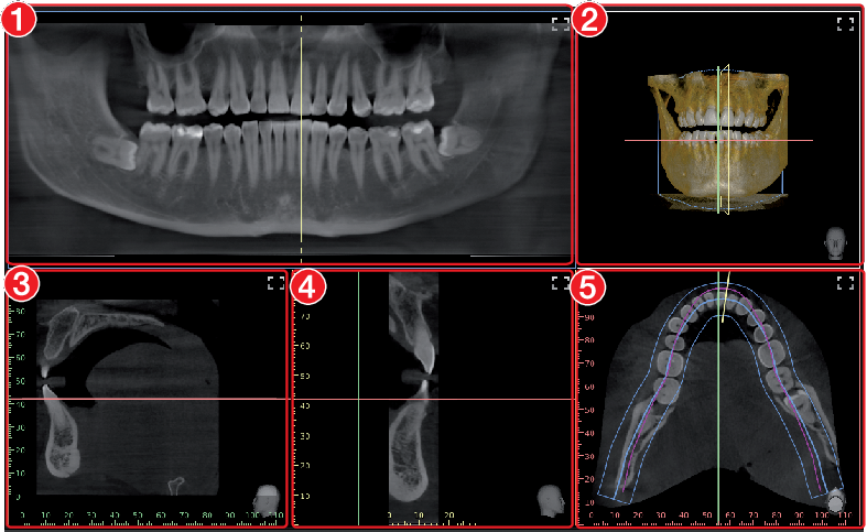
|
TSA view | |
|---|---|
 | With the TSA view, several transversal layer images (TSA) are displayed in addition to the panoramic view. The TSA slices are numbered (bottom left). The numbering allows adjacent TSA slices to be recognised, which makes drawing the nerve channel easier. 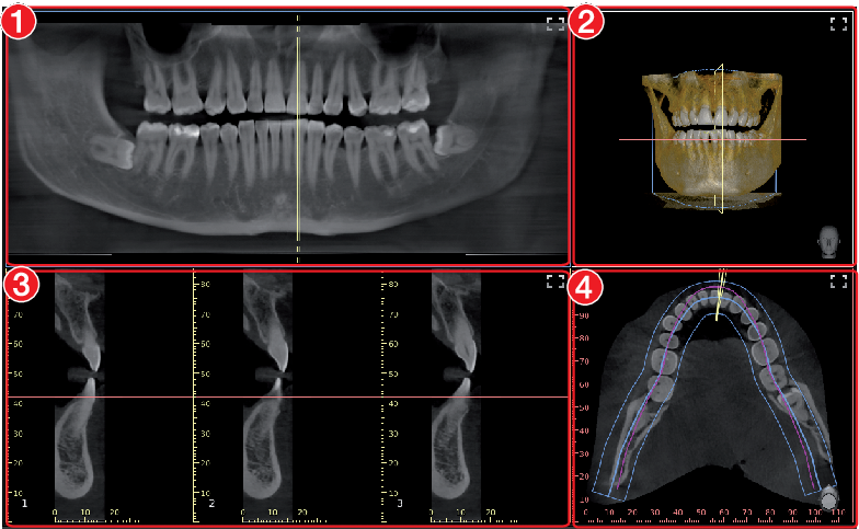
|
If the mouse cursor is positioned above one of the TSA slices, this TSA slice is highlighted in colour in the other views.
MPR view | |
|---|---|
 | With the multiplanar reconstruction (MPR), any two-dimensional layer and slice images can be displayed. 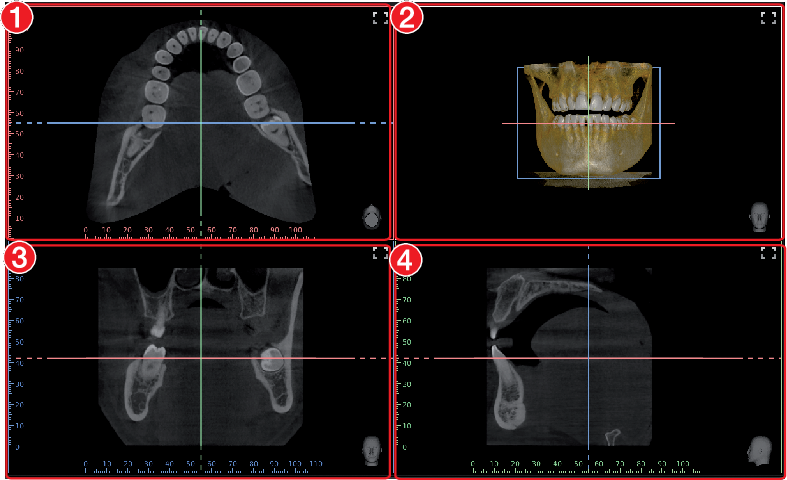
|
Panoramic
 | Anatomically adjusted panoramic curve | Anatomically adjusted curve shape is automatically placed on the axial layers running through the mandible and maxilla. The anatomically adjusted curve cannot be changed. |
 | Standard panoramic curve, lower jaw | The standard curve form is automatically positioned on an axial layer that extends through the lower jaw |
 | Standard panoramic curve, upper jaw | The standard curve form is automatically positioned on an axial layer that extends through the upper jaw |
 | Standard panoramic curve on current slice plane | The standard curve form is manually positioned on the current axial slice. The centre point of the arch of the jaw is manually positioned by the user. |
 | User-defined panoramic curve on current slice plane | A free curve form is manually positioned on the current axial slice. The individual points of the panoramic curve are manually positioned one after the other. |
| Abort creation of user-defined panoramic curve | During creation of the user-defined panoramic curve the points that have already been positioned are deleted again. |
 | Panoramic thickness | The layer thickness of the panoramic curve can be freely adjusted with a slider. With a lower thickness the panoramic view is sharper but noisier. With increasing thickness the noise is reduced, but the panoramic view appears less sharp. Here, with increasing thickness the panoramic view approaches the character of a panoramic X-ray image (2D). |
The panoramic curve (except for the anatomically adjusted panoramic curve) can be moved and edited once it has been positioned.
The panoramic curve is also shown in the annotations.
(anatomically adjusted),
(maxilla) or
(mandible).
.
.
TSA
 | Select TSA layout | Flyout for selection of the layouts or the number of transversal slices that are to be displayed (maximum of 6 rows x 10 columns) |
 | TSA distance | With the aid of a slider the distance between the transversal slices can be changed (0.2 mm - 10.0 mm). |
 | TSA length | With the aid of a slider the length of the transversal slices can be changed (2 mm - 200 mm). |
 | TSA width | With the aid of a slider the width of the transversal slices can be changed (0.1 mm - 10.0 mm). |
The TSA settings are saved when the user switches to a different view, closes the image or exits the software.
.
The TSA slices are displayed and shown in the other views.
to move the TSA slices.
to tilt the TSA slices.
The TSA slices can be tilted by max.
±
75°.
MPR
 | Thickness of MPR slices | The thickness of the MPR slices can be changed with the slider. The lower the thickness, the sharper but the noisier the image. The higher the thickness, the lower the noise but the less sharp the image. |
The adjustment always applies to all slices (sagittal, coronal, axial) of an MPR view.
The set thickness is saved when the user switches to a different view, closes the image or exits the software.
Nerve canal
 | Create a nerve canal proposal | A proposal for the position of the nerve canal is calculated automatically (only visible if the calculation of the nerve canal proposal is activated in the configuration, see Nerve canal detection ). The proposal must be verified by a trained professional. |
 | Draw nerve canal in image | The nerve channel can be drawn in all two-dimensional views (panoramic view and slices). The individual anchor points of the nerve channel are manually positioned one after the other. Once the nerve channel has been drawn, it is visible as a semitransparent "tube" in all views, including the volume view. It is saved as an annotation. |
| Delete nerve channel | Deletes a nerve channel that has already been created. To do this, the nerve channel must be selected in a view or in the annotations. |
In the list of annotations, the drawn nerve channel can be called up again. When it is called up, the slices and the panoramic view are reset to the representation in which the nerve channel was drawn.
The nerve channel can be drawn in all two-dimensional views (slices and panoramic view) and is displayed in all views (including the volume view).
A nerve canal proposal can be calculated automatically (see also Nerve canal detection ).
WARNING
The nerve canal can be displayed or drawn incorrectly.
The nerve can be injured during the treatment.
Only use the drawn nerve canal as a guide.
During the treatment pay attention to the actual location and path of the nerve canal.
.
.
.
.
Volume
There are different display options in the volume view:
X-ray | Simulated X-ray projection image |
Maximum value | Simulated X-ray projection image, the brightest point is shown for every image point in the viewing direction |
ISO layer | View of the volume combining two opaque surfaces: soft tissue (brown) and bone structures (white) |
3D | 3D rendering |
User-defined | 3D rendering with simulated illumination. Skin tissue and muscle tissue are displayed in addition. |
In the 3D view different tissue types are shown with different colours. The visibility of the tissue types can be adjusted with the relevant slider.
Tissue types in the 3D view:Bone
Dentine
Enamel
Metal
Skin
Muscle
Bone
Dentine
Enamel
Metal
The colours for the tissue types can each be chosen via a flyout in the User-defined view.
Slice
Slice | Display of the slice planes in the volume view | |
|---|---|---|
 | Show slice plane edges only | Only the edges of the slice planes are displayed (may be masked by the volume display). |
 | Show slice planes with semitransparent surface | The slice planes are displayed with colour-filled surfaces (may be masked by the volume display or other slice planes). |
 | Hide slice planes | The slice planes are not visible. |
Axial | Region above or below the slice plane is hidden. | |
Sagittal | Region to the left or right of the slice plane is hidden. | |
No slice | Everything is visible, all regions are displayed. | |
Reverse | Hidden regions are inverted (top/bottom or left/right). | |
Display
These tools allow you to alter the image view.
The zoom tools change the size that the image is displayed on the light table. The settings are not saved.
The settings for rotating and inverting an image are saved.
The zoom tools in CBCT images (3D) can be used for all views. If the option Same zoom in all views is enabled, then all views, except panoramic and volume view, are displayed at the same zoom factor. If the option is disabled, each view can be changed individually. The tools for image rotation and mirroring are not available for CBCT images (for information on how to rotate a slice, see Navigating in CBCT images (3D) ).
Zoom | |
|---|---|
 | This matches the size of the image to the size of the window. |
 | This magnifies the image so that one screen pixel equals one image pixel. Is displayed centred in the window. |
 | The current zoom factor is displayed. A defined zoom factor can be selected. |
 | The zoom can be adjusted to any required setting via the slider. You can also use the mouse wheel to adjust the zoom. |
Rotate image | |
|---|---|
 | Rotate the image anti-clockwise by 90°. |
 | Rotate the image clockwise by 90°. |
Mirroring | |
|---|---|
 | Horizontally invert the image |
 | Vertically invert the image |
Image corrections
The image brightness, contrast and gamma can be corrected. As you adjust the sliders, you can see the changes directly in the image itself.
 | Adjust the image brightness |
 | Adjust the image contrast |
 | Adjust the image gamma value < 1: Bright areas become darker > 1: Dark areas become brighter |
Mouse pointer icon | |
|---|---|
 | Brightness and contrast can also be changed directly in the image using the left mouse button. For this purpose, go to Toolbox > Image corrections and enable the option Mouse mode . When the left mouse button is held down, making horizontal motions over the image changes the brightness, while vertical motions adjust the contrast. The sliders in the toolbox move along accordingly. This option can be enabled separately for 2D X-ray/video images and for 3D X-ray images. It is preset for 2D X-ray/video images. |
Filter
Filters facilitate diagnosis when analysing X-ray images by highlighting interesting structures so that they can be more easily identified. Here, there are different filters for the different image types (e.g. intra, panoramic, cephalometric, ...).
Depending on the X-ray image type, the matching filters are automatically displayed in the toolbox.
Filters for intra X-ray images | ||
|---|---|---|
 | Intraoral Fine | This increases the contrast for fine structures. |
 | Intraoral Caries 1 | This increases the contrast for areas in which caries can be found. Fine structures are emphasised. |
 | Intraoral Caries 2 | This increases the contrast for areas in which caries can be found. Coarser structures are emphasised. |
 | Intraoral Endo | For optimal visualisation of the file in the root canal. |
 | Intraoral Perio | The contrast is increased in areas of the periodontal spaces. |
 | Intraoral High Diagnostic | Increased contrast for optimal visualisation of objects of a specific size. |
 | Intraoral Noise Reduction | This cancels disruptive image noise and maintains image sharpness. |
Filters for panoramic X-ray images | ||
|---|---|---|
 | Panoramic fine | This increases the contrast for fine structures. |
 | Panoramic Standard | This increases the contrast for relatively coarse structures. |
 | Panoramic High Diagnostic | Increased contrast for optimal visualisation of objects of a specific size. |
 | Panoramic Noise Reduction | This cancels disruptive image noise and maintains image sharpness. |
Filters for cephalometric X-ray images | ||
|---|---|---|
 | Ceph Fine | This increases the contrast for fine structures. |
 | Cephalometric 1 | This increases the contrast for relatively coarse structures. |
 | Cephalometric PA | Posterior-anterior: View from back to front; this considerably increases the contrast for coarse structures. |
 | Cephalometric High Diagnostic-10 | Increased contrast for optimal visualisation of 10 mm objects. |
 | Cephalometric High Diagnostic 5s | Increased contrast for optimal visualisation of 5 mm objects. Subsequent image sharpening via unsharp mask filter. |
 | Cephalometric High Diagnostic-5g | Increased contrast for optimal visualisation of 5 mm objects. Subsequent image sharpening via Gaussian filter. |
 | Cephalometric Noise Reduction | This cancels disruptive image noise and maintains image sharpness. |
Filters for cephalometric X-ray images | ||
|---|---|---|
 | Invert | The brightness values are inverted. The filter can be combined with any other filter for X-ray images. |
On video images filters are only available for images taken with the Proof camera.
Filters for video images recorded with a proof camera | ||
|---|---|---|
| Caries filter | Analyses the autofluorescence of the substances. The colour scale and the numeric values provide reliable information on carious lesions. The colour scheme legend can be called up with |
| Prophylaxis view | Original image recorded by the proof camera |
Histogram
The histogram shows the brightness distribution of the image.
Histogram windowing allows you to alter the image's grey scale values. The black limit shows the percentage of grey scale values changing to black, and the white limit shows the percentage of grey scale values changing to white. The limits can be altered to suit your requirements. The settings you have applied will be immediately apparent in the X-ray image on the light table.
The changes this makes to the image can emphasize structures that are otherwise too small to be distinguished by the human eye so that they can be identified.
If a filter is used then the histogram is automatically recalculated.
The image processing can be saved with the changes you have made (see Managing default image settings). To prevent the quality of future X-ray images being impaired excessively by the saved image processing, both limits are restricted to 10% on saving.
 in the middle of the region and move it with the mouse button pressed.
Measurements
The size and resolution of the image depends on the image acquisition device (see the operating instructions of the respective device).
2D X-ray images: In order to estimate lengths and angles in 2D X-ray images, the image needs to be calibrated with the aid of a reference image object. Despite calibration, this estimation does not show the accuracy of a measurement and must not be used as a measured result. The accuracy depends greatly on the projection distortion of the object on the image detector area.
Video image: In video images, lengths and angles cannot be estimated to scale.
Panoramic X-ray images are not suitable for measuring due to their projection technique.
CBCT image (3D): The calibration is calculated geometrically. Measurements are only possible in the slices (axial, sagittal, coronal and TSA), but not in the volume view or panoramic view. The length and angular values in displayed layers (MRI) are calculated on the basis of the voxel dimensions defined in the 3D image data set (measuring unit e.g. mm). The accuracy with regard to the anatomical relationships is dependent on these voxel dimensions. The values calculated in the software therefore only reflect the relationships of the voxel data in defined accuracy. The display accuracy is equivalent to 50% of the last decimal place (e.g. if the resolution is 0.1 mm the accuracy is 0.05 mm).
The following measurements can be performed:
 | Simple line (start and end point) |
 | Polyline (start, intermediate point and end point) |
 | Angle (between two straight lines) |
The measurements are saved as an annotation.
The image needs to be calibrated for the measurements. The symbol shows the calibration type:
 | Calibration, geometrically calculated: The known geometry of the image acquisition system (e.g. resolution of the image acquisition mode, magnification factor) is incorporated in the calculation. |
 | Calibration with a reference object: The known size of a reference object included in the image has been measured and saved. The reference object must be located in the direct area of the area being measured during imaging. |
Rulers can be displayed on calibrated images. Rulers are not available for uncalibrated images or for the measurement unit 'pixels' (px).
 | Show rulers |
 | Hide rulers |
WARNING
Incorrect measurement result due to projection distortion or incorrect calibration
Perform calibration with a reference object.
Keep the projection distortion as low as possible during the X-ray acquisition.
Do not use a panoramic image for the measurement.
.
 .
.
.
.
.
.
.
.
 , hold the mouse button and move it.
.
.
, hold the mouse button and move it.
.
.
Drawings
Drawings can be inserted into the image. All drawings are saved as annotations.
The following drawing tools are available:
 | Create free-hand drawing |
 | Create a line |
 | Create an arrow |
 | Create a rectangle |
 | Create an ellipse |
. . . . . pressed and move the drawing.The anchor points of pre-hand drawings cannot be edited.
, hold the mouse button and move it. . .Edge mask
X-ray images can be masked at the edges to prevent the occurrence of effects that may hinder diagnosis. The area beyond the edge mask is hidden.
The edge mask can be activated or deactivated. The edge mask is automatically activated for intraoral X-ray images.
The edge mask and background colour can be configured for every X-ray station.
Implants
For visualisation purposes, implants can be schematically inserted in two-dimensional and three-dimensional images. This function is included in VistaSoft Basis.
Implant planning can be done using VistaSoft Implant / Guide. This requires the purchase of a licence for VistaSoft Implant / Guide (see Purchasing a licence for VistaSoft Implant & Guide).
In a CBCT image the implant can only be added in the slices and in the panoramic view, but not in the volume view. It is shown in all slices and views if it is in the indicated view or slice.
There are two types of implants that can be inserted:
 | Standard implant (length and diameter can be freely defined) |
 | Implant from manufacturer's database, see Importing implant packages |
The implant is depicted as a cylinder (standard implant) or a 3D model (manufacturer implant, see Importing implant packages). If the implant is activated then it can be aligned via the two control points (circles).

The implant is saved as an annotation. With standard implants it is possible to change the size and colour of the implant, while on manufacturer's implants only the colour can be changed (see Annotations).
. . . orPress the Del key. .Annotations
All measurements, nerve channels and implants of an image are saved as annotations. The annotations are displayed in the list and can be called up again.
When an annotation is called up on a 3D image, the views/slices return to the view in which the annotations were drawn.
Every measurement is indicated in the list with the type, colour and numerical value.
Type of annotation | |
|---|---|
| Simple line |
| Polyline |
| Angle |
 | Nerve channel (3D only) |
| Implant |
| Panoramic curve |
next to an annotation in the list.
.
.
.
Managing default image settings
Default image editing settings are saved for every X-ray station (see also Image processing ). Every newly created image will automatically be displayed on the light table with these default settings.
The default settings can also be saved via the light-table menu with the settings on an image:
and then
.
Editing a surface scan
On the light table it is only possible to view the surface scans (see Rotating the surface scan ). In order to edit a surface scan, it will need to be opened in the VistaImpress module.
 .
.
Each case may contain up to five surface scans. The scans are displayed individually in the image inspector.
Printing images
Images that are open on the light table can be printed out using the function Print image .
The following print settings can be set up in the dialog window:
Printer: | Select printer. A further printer can be set up in the configuration (see Configuring the DICOM printer ). | |
Original image size: | Prints the images in original size; only calibrated images can be selected. If necessary you may need to adjust the paper size in the printer settings. If the image is too large for the print format then the image is cropped. | |
Landscape format: | Switches the print layout from portrait to landscape. | |
Colour: | Prints the images in colour. If this setting is disabled then the prints will be in black and white. | |
Copies: | Enter the number of copies. The default setting is 1. | |
Printer view: | ||
Active image | The active image on the light table (image is highlighted, the frame is visible) is printed. | |
Image area | All images that are open on the light table are printed. The layout corresponds to the one on the light table. | |
Light table | The light table is printed out with all images that are open. The layout corresponds to the one on the light table. In contrast to Image area , the complete light table is printed out – including areas containing no image frames. | |
Tabular | All images on the light table are printed. The number of columns can be adjusted under Images per line . | |
Print settings | DICOM printers only: printer settings for the current print order. For information about making general changes to the print settings see Configuration . | |
Annotations | Information about the image, patient and practice that can also be printed. | |
Contents | Selection list of the information; this is stated with placeholders ( %...% ) and then filled with the current information during printing. | |
Position | The annotations can be positioned relative to the image (e.g. top right corner of the image) or to the side (e.g. header) | |
Size | Font size for annotations | |
The print settings can be saved as a profile, see Using print profiles .
.
On CBCT images (3D) only the print view Actives image is possible. Auxiliary lines and rulers are not printed.
Setting up the annotations for print output
Annotations can be added for printing (e.g. patient name, tooth, diagnosis). The annotations set up are retained in the dialog window.
.
again and select the content, position and size.
 .
.
.
.
Using print profiles
Colour printing
Greyscale printing
Changes to the print settings are saved in the active profile when the dialog window is closed. The profiles are saved separately for each practice.
Further print profiles can be created, edited and deleted.
next to the profile name.
.
Using VistaSoft Cloud
You can use the VistaSoft Cloud feature to upload acquired images to the VistaSoft Cloud. Using the uploaded image data, the recipients can view and discuss the image data.
Recipients can access the VistaSoft Cloud via a browser.
CAUTION
Personal injury may occur as the result of altered images or data (cybersecurity)
Do not use data for diagnosis
- All data is anonymized before being transferred to the cloud. There is therefore no way for recipients to match the data to the patient.
- A secure protocol (HTTPS) is used for data transfer.
Because image data in lossy file formats (such as JPEG) can be uploaded to the VistaSoft Cloud, it is not possible to make a diagnosis.
Uploaded images are deleted after 30 days. So the VistaSoft Cloud is not suited for use an archive.
A cloud case is created for each image that is uploaded to the cloud. The cloud cases can be viewed using the overview at any workstation of a multi-station installation. To do so, the practice through which the image was uploaded to the cloud must be logged in to the workstation.
The recipients for whom the image data is being uploaded to the cloud can access the cloud via a browser.
Uploading an image to the cloud
A cloud case is generated every time image acquisitions are uploaded.
The Multiple selection function in the image inspector can be used to simultaneously upload multiple images to the cloud (see Multiple selection ). When this is done, only one cloud case will be stored for all selected images.
in the light table menu.
Do not include any patient data in the comment as this would compromise anonymity.
 icon in the image inspector.
The recipient receives an email containing a link to the cloud case.
next to the preview image for each X-ray image that is to be uploaded.
.
icon in the image inspector.
The recipient receives an email containing a link to the cloud case.
next to the preview image for each X-ray image that is to be uploaded.
.
Do not include any patient data in the comment as this would compromise anonymity.
icon in the image inspector.
The recipient receives an email containing a link to the cloud case.Finding and displaying cloud cases
All of the cloud cases are shown in the overview. If several practices have been created then only the cloud cases for the currently logged-in practice will be visible.
New comments are indicated in the menu bar by means of a button with counter.
The amount of data remaining is shown in the upper right-hand corner of the overview. The available amount depends on the data plan that was booked.
| Show VistaSoft Cloud cases |
 | Counter for new comments |
Editing a cloud case
The properties and preview images of the updated image data can be displayed for every cloud case. The comments can be read, and new comments can be added.
Deleting a cloud case
in the menu bar.
Displaying the X-ray report
The X-ray report displays all images, along with the date, exposure values, X-ray station and indications.
in the ribbon.
Change practice (surgery)
If multiple practices (surgeries) have been created you can switch between them.
.Using the VDDS-media interface to practice management program
CAUTION
Personal injury is possible due to wrong assignment of image data to a patient
Check the right assignment of the image data (e. g. during image import, change of patient data new assignment of image data to a patient).
Observe the information displayed in the software.
Importing patient data from PVS into the Imaging Software and requesting image acquisitions, see Importing patient data.
Opening a patient image from PVS in the Imaging Software, see Importing patient data.
Transferring images from the Imaging Software to PVS and transferring changes to images (see Transferring images to the practice management software, Multiple selection.
The VDDS media interface must be configured in the practice management program and in the imaging software for this purpose (see Interfaces).
For information about the configuration and handling of the interface in the practice management program, please refer to the relevant PVS handbook.
Creating a support file
In the event of a fault a support file can be created. This can be forwarded to the support/service technician for diagnosis.
>
in the software.
Using 3Shape integration
If the feature “3Shape integration” is activated (see 3Shape integration), then VistaSoft can be used to initiate a surface scan with a 3Shape intraoral scanner. This 3Shape case is linked to the patient in VistaSoft and can be opened via the image inspector in 3Shape.
Creating a 3Shape case
in the menu bar.After the next login for the patient the 3Shape case is displayed in the image inspector.
Opening a 3Shape case
3Shape cases that have been created via the 3Shape integration are called up during login of the patient and displayed in the image inspector with the 3Shape symbol. The data is managed in 3Shape and can be opened at any time again in 3Shape via the image inspector.
The case is opened in 3Shape and can be edited.
VistaSoft Connect
VistaSoft Connect receives orders from third-party applications to generate images using imaging device systems from Dürr Dental.
The job data is transmitted from the calling third-party application to VistaSoft. VistaSoft creates a new patient on the basis of the job data or assigns the job to an existing patient.
Installing VistaSoft Connect
MobileConnect cannot be combined with VistaVox.
Launching the software for the first time
The installation is completed when the software is run for the first time.
Here, a setting is chosen that cannot be changed again afterwards:Operating mode (single workstation, server or client / terminal server):
Depending on the operating mode, the system then either creates the database or sets up the connection to the database on the server.
For a terminal server installation, the environment variable is defined (client name or username).
Configuration
Practice VistaSoft Connect
Database directory C:\VistaSoftData
User management deactivated
Using VistaSoft Connect
VistaSoft Connect can only be used if the configuration requirements have been met, see Limitations of the minimal Connect interface.
Patient ID
First name
Surname
Date of birth
Name: VistaSoft Connect Patient
Patient ID: Date and time of the task (YYYYMMDD-HHMMSS)
Date of birth: Date of the task
If no patient is logged in, the patient is registered automatically and acquisition of the X-ray image starts. By completing the VistaSoft Connect task, the VistaSoft Connect patient is logged out and the image data defined in the task is exported. It can then be imported by the third-party application.
If Automatic dose calculation is activated (see Configuration) and the X-ray image acquisition device supports the function, the incident dose at the image receiver is also sent to the third-party application together with the image data.
If the minimal interface is activated in the configuration (see VistaSoft Connect) and the software interface is closed (only active in the taskbar), only the minimal interface opens during a VistaSoft Connect task (see Use the minimal interface). Logging the patient in/out then takes place in the background.
You can set the retention period for image data in VistaSoft Connect, see Configuration.
Creating an image with VistaSoft Connect
 VistaSoft Complete Connect order.
The image data is exported to the third-party application.
The patient is logged out.
Creating an image in the SmartScan workflow with VistaSoft Connect
The SmartScan workflow with VistaSoft Connect is not suitable for single workstation installation.
. , ascending audio signal is heard (if configured).For more information about this refer to the installation and operating instructions for the device.
in the image archive, enter X-ray parameters, see Enter X-ray parameters/image information. VistaSoft Complete Connect order.The image data is exported to the third-party application.
The patient is logged out.
Use the minimal interface
The image data is exported to the third-party application. The minimal interface is closed.
A windows notification informs you that the task has been concluded.
A Windows notification appears when the automatic image plate quality check changes the state of the image plate.
Limitations of the minimal Connect interface
Only one practice is created
User management is deactivated (only one user without password)
X-ray parameters are not mandatory (see Practices )
Importing images
Importing an image from the device memory (standalone / retrieve)
If there is an image on the device memory of a device, it can be imported to the active Connect task.
in the imaging window.The image data is exported to the third-party application.
The patient is logged out.
Importing an image from the image cache (cache image import)
If it is not possible to transfer an image to the server or to the third-party application after it is created, then the image will be saved in the image cache of the workstation (see Image cache).
 in the imaging window.
The image data is exported to the third-party application.
The patient is logged out.
VistaSoft Inspect acceptance and consistency check
With VistaSoft Inspect it is possible to perform acceptance tests, consistency checks and partial acceptance tests on the image reproduction and X-ray system in full. No third-party software is required for this.
With VistaSoft Inspect you can carry out the following tests:Acceptance test of the image reproduction and X-ray system
Consistency checking of the image reproduction and X-ray system
Partial acceptance test of the image reproduction and X-ray system
Here, VistaSoft Inspect detects which device is being tested and adapts the test that is to be performed to the requirements of the device.
VistaSoft Inspect office the additional opportunity to check the condition of the image plates:DIN 6868-151: Acceptance test in accordance with RöV on dental X-ray equipment
DIN 6868-161: Acceptance test in accordance with RöV of dental X-ray units for digital volume tomography
DIN 6868-157: Acceptance test and consistency check of the image playback system
DIN 6868-5: Consistency check according to X-Ray Ordinance (RöV) on dental X-ray equipment
DIN 6868-15: Consistency check in accordance with the X-Ray Ordinance (RöV) on dental X-ray equipment for digital volume tomography
DIN 6868-157: Acceptance test and consistency check of the image playback system
German X-ray Directive (Röntgenverordnung, RöV)
Guidelines for Expert Qualifications (Sachverständigen-Richtlinie, SV-RL)
Quality Assurance Guidelines (Qualitätssicherung-Richtlinie, QS-RL)
Specialist Knowledge Guidelines (Fachkunde-Richtlinie, (FK-RL)
Notes on use
From the start page of VistaSoft Inspect you can switch directly to the different checks:
 | Monitor test | Checks of the image reproduction systems |
 | Acceptance and consistency checks | Checks of the X-ray systems |
 | Plate surface quality check |
The software checks the validity of the checks and reminds you when checks are due (provided this has been configured, see Acceptance and consistency check).
If no checks are present or the checks are no longer valid, the number of due checks is displayed.

The left-hand part of the menu bar contains the navigation. Here you can switch directly from the current position to the higher levels.
The configuration and help functions can be accessed via the area on the right of the menu bar:
Right-hand section | ||
|---|---|---|
| Configuration (see Configuring VistaSoft Inspect) | |
| Help | |
| Display help | |
| Create support file (see Creating a support file) | |
| Supported devices | |
| Show Info dialog | |
Launching VistaSoft Inspect
By clicking on the icon on the desktop
Go to the entry in the start menu: Start > All programs > VistaSoft Inspect > VistaSoft Inspect
Configuring VistaSoft Inspect
For information about further configuration options refer to VistaSoft Inspect configuration overview
If a corresponding configuration is already present VistaSoft, e.g. X-ray stations, this will be adopted by VistaSoft Inspect.
Creating X-ray stations
The X-ray stations from VistaSoft are automatically displayed in VistaSoft Inspect.
If X-ray stations are created in VistaSoft Inspect they are displayed automatically in VistaSoft.
An X-ray station always comprises the following:X-ray emitter
Image acquisition device
Operator information
Here, e.g. an X-ray emitter can be combined with different image plate scanners or one image plate scanner can be combined with different X0ray emitters into multiple X-ray stations.
The X-ray station marked as the favourite is displayed first in the selection list when the tests are started.
In the X-ray station configuration you can create, configure and delete X-ray stations. This works in exactly the same way as in the imaging software. See X-ray stations .
>
X-ray stations
.
Configuring the monitor test
If the work station is a diagnosis station, the monitor check must be performed at regular intervals. The basic setting that the work station is a diagnosis station is performed in the configuration , see Acceptance and consistency check.
In the case of a multi-station installation, the monitor check are stored centrally on the server.
In the configuration you can edit information about the workstation in the practice/clinic. These are saved and reused during subsequent tests.
Monitor test. Acceptance and consistency checks
The start page of the acceptance and consistency checks provides an overview of the X-ray stations and the associated checks and tests.
On opening, the list of X-ray stations is sorted by the due date of the checks/tests. If a check/test is due at an X-ray station, the status is highlighted with .
In the details area the current status and the progress of the checks/tests are displayed.
Via the button Configure X-ray stations... you can jump directly to the configuration screen for the X-ray stations (see also Creating X-ray stations).
An access code (technician password) is required in order to perform an acceptance test and a partial acceptance test. The access code is required once after every restart of the software if an acceptance test or partial acceptance test is being processed.
The access code is made up as follows: current date (day and month) in reverse sequence. For example: 03 May = 03.05. Access code: "5030"
Performacceptance test
Before starting up an X-ray system for the first time
When moving the system to a different location
If the operating company changes (additional expert qualifications are required in this case)
The acceptance test for the X-ray system must be performed by a certified service technician with proven expertise and specialist knowledge.
Performing the acceptance test for the image reproduction system
Ensuring that the required image quality is achieved with the lowest possible radiation exposure
Defining the operator and device data
Determining and assessing the light intensity and illuminance of the image reproduction device and its surroundings
Visual assessment via test images
Definition of reference values for the consistency checks
Monitor test. Performing the acceptance test for the X-ray system
Ensuring that the required image quality is achieved with the lowest possible radiation exposure
Defining the operator and device data
Definition of reference values for the consistency checks
Quality assurance for the system
You can exit from the acceptance test at any time using the navigation bar. This interrupts an ongoing acceptance test, but the test can be continued at a later point in time.
Acceptance and consistency tests.The questions posed in the acceptance test depend on the X-ray system.
 . (See also Notes on creating an X-ray image)
 to select any other image as a reference image.
As long as the acceptance test has not been completed, new images can be imported at any time.
.The test can only be completed if all fields have been properly filled in. If the mandatory fields are not filled in or they are only filled in partially, the symbol appears next to the tabs.
Performing a consistency check
A complete consistency check comprises the consistency check of the image reproduction system and the consistency check of the X-ray system.
Performing a consistency check on the image reproduction system
The consistency check on the image reproduction system (IRS) in accordance with DIN 6868-157 comprises two different test procedures, which are normally performed every working day and on a yearly basis.
Daily test: visual inspection of a test image on the image reproduction device
Yearly test: measurement of the luminous density and illuminance of the image reproduction device and its surroundings (based on the requirements of the acceptance test)
Monitor test. Performing a consistency check on the X-ray test
Consistency checking is carried out by taking X-ray exposures of the test phantom using the same dosing parameters as used for the acceptance test (benchmark values). The recorded consistency check image (test exposure) is compared with the X-ray of the acceptance test (reference image acquisition), and the measurements are checked for possible deviation from the benchmark values (reference values). The consistency check image is clearly labelled by the software.
The requisite tests are determined by the local law. Carry out testing in accordance with local rules and regulations.
You can exit from the consistency check at any time using the navigation bar. This discards the commenced consistency check and the check cannot be continued at a later point in time.
A consistency check can only be performed if a completed valid acceptance test/partial acceptance check result is available.
Acceptance and consistency tests.The questions posed in the consistency check depend on the X-ray system.
New images can be imported at any time. Here, the previously imported image is overwritten.
. (See also Notes on creating an X-ray image)The test can only be completed if all fields have been properly filled in. If the mandatory fields are not filled in or they are only filled in partially, the icon appears next to the tabs.
Performing a partial acceptance check
The scope of a partial acceptance test is defined by the scope and context of changes made to the system.Depending on the nature of the changes, a consistency check or overlapping measurement to validate the relevant criteria will also be required.
Details about this can be found in the Guidelines for Expert Qualifications (Sachverständigen-Richtlinie, SV-RL) and the Quality Assurance Guidelines (Qualitätssicherung-Richtlinie, QS-RL).
A partial acceptance check can only be performed if a completed acceptance test result or partial acceptance check result is available.
Here, the partial acceptance check is pre-populated with the data from the previous test (last acceptance or partial acceptance check). You only need to edit entries that need to be changed.
Acceptance and consistency tests.The questions posed in the partial acceptance check depend on the X-ray system.
. (See also Notes on creating an X-ray image) to select any other image as a reference image.As long as the acceptance test has not been completed, new images can be imported at any time.
.The test can only be completed if all fields have been properly filled in. If the mandatory fields are not filled in or they are only filled in partially, the symbol appears next to the tabs.
Notes on creating an X-ray image
The tests of the X-ray system (acceptance test, partial acceptance check and consistency check) are made up of various tabs. A test always opens with the tab X-ray image acquisition.
The X-ray image acquisition tab has a similar layout to the user interface of the imaging software.
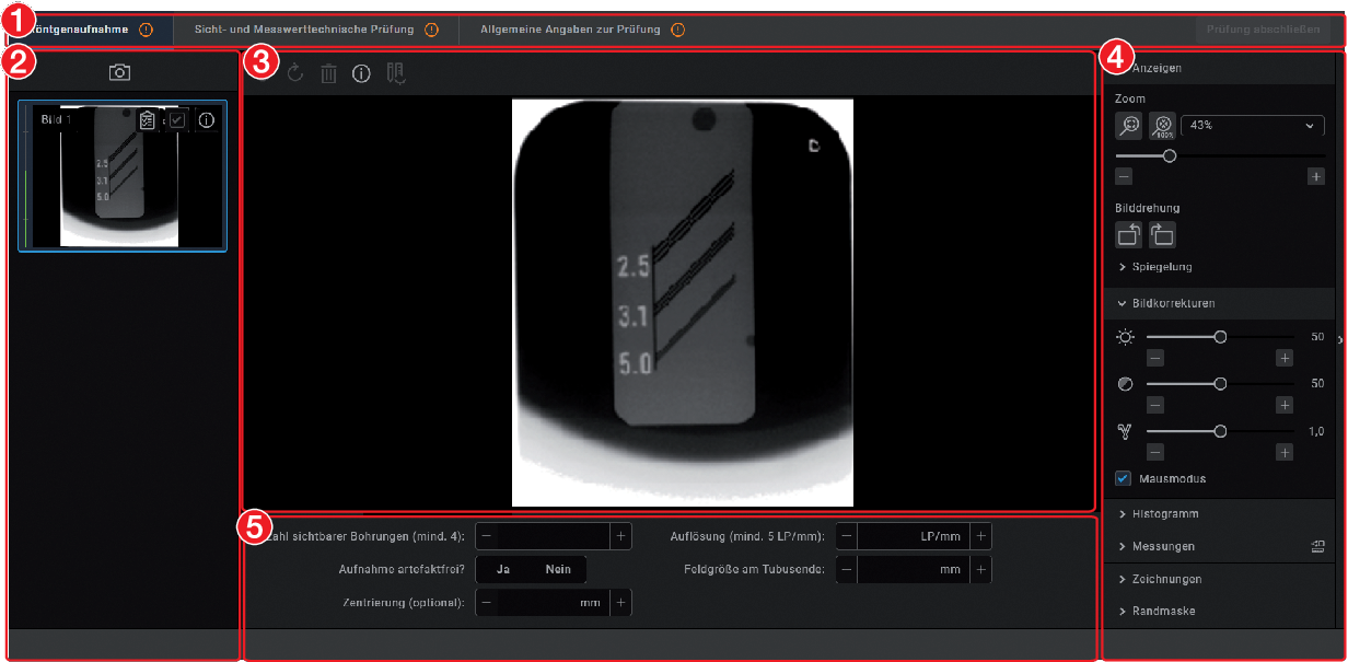
- 1Tabs for the test
- 2Image inspector
- 3Light table
- 4Toolbox
- 5Image details
Image inspector
All of the images for the current test are displayed in the image inspector. The image designation is displayed on the images if it is entered in the image information
. It is possible to select the reference image and edit image information as long as the test has not yet been completed.
| Displaying and editing image information |
| Image is the reference image for the test |
 | Image is not the reference image for the test |
Light table
If an image is selected in the image inspector (blue surround) then this image is displayed on the light table. Only one image can be displayed at a time on the light table of the acceptance checks and consistency checks.
CBCT images are always displayed as an axial MPR slice. You can navigate in the view using the mouse:
| Scroll layers | Press and hold the left mouse button in the view to scroll through the layers. The number of the layer is displayed on the bottom left-hand during scrolling. |
| Tilt slice plane | Press and hold the left mouse button in the edge region of the view to turn the slice plane. |
Questions and details for the active image are displayed under the light table.
The light-table menu features various commands for the images displayed on the light table:
| Repeat or undo actions | |
| Delete image | |
| Displaying and editing image information | |
 | Displaying the currently acquired image and the reference image side-by-side or one above the other (for the consistency check only) | |
 | ||
| Displaying or hiding measurements | |
| ||
Toolbox
The toolbox contains tools for editing the images on the light table.
The tools are divided into the following groups and can be expanded or collapsed by clicking :Dose equivalent (only if equivalent dose measurements are enabled in the configuration)
The edited image is saved with the preview in the image inspector as soon as the user switches to the next registration card of the test or the test itself is closed.
Display
These tools allow you to alter the image view.
The zoom tools change the size that the image is displayed on the light table. The settings are not saved.
The settings for rotating and inverting an image are saved.
The zoom tools in CBCT images (3D) can be used for all views. If the option Same zoom in all views is enabled, then all views, except panoramic and volume view, are displayed at the same zoom factor. If the option is disabled, each view can be changed individually. The tools for image rotation and mirroring are not available for CBCT images (for information on how to rotate a slice, see Navigating in CBCT images (3D) ).
Zoom | |
|---|---|
| This matches the size of the image to the size of the window. |
| This magnifies the image so that one screen pixel equals one image pixel. Is displayed centred in the window. |
| The current zoom factor is displayed. A defined zoom factor can be selected. |
| The zoom can be adjusted to any required setting via the slider. You can also use the mouse wheel to adjust the zoom. |
Rotate image | |
|---|---|
| Rotate the image anti-clockwise by 90°. |
| Rotate the image clockwise by 90°. |
Mirroring | |
|---|---|
| Horizontally invert the image |
| Vertically invert the image |
Image corrections
The image brightness, contrast and gamma can be corrected. As you adjust the sliders, you can see the changes directly in the image itself.
| Adjust the image brightness |
| Adjust the image contrast |
| Adjust the image gamma value < 1: Bright areas become darker > 1: Dark areas become brighter |
Mouse pointer icon | |
|---|---|
| Brightness and contrast can also be changed directly in the image using the left mouse button. For this purpose, go to Toolbox > Image corrections and enable the option Mouse mode . When the left mouse button is held down, making horizontal motions over the image changes the brightness, while vertical motions adjust the contrast. The sliders in the toolbox move along accordingly. This option can be enabled separately for 2D X-ray/video images and for 3D X-ray images. It is preset for 2D X-ray/video images. |
Histogram
The histogram shows the brightness distribution of the image.
Histogram windowing allows you to alter the image's grey scale values. The black limit shows the percentage of grey scale values changing to black, and the white limit shows the percentage of grey scale values changing to white. The limits can be altered to suit your requirements. The settings you have applied will be immediately apparent in the X-ray image on the light table.
The changes this makes to the image can emphasize structures that are otherwise too small to be distinguished by the human eye so that they can be identified.
If a filter is used then the histogram is automatically recalculated.
The image processing can be saved with the changes you have made (see Managing default image settings). To prevent the quality of future X-ray images being impaired excessively by the saved image processing, both limits are restricted to 10% on saving.
in the middle of the region and move it with the mouse button pressed.
Measurements
The size and resolution of the image depends on the image acquisition device (see the operating instructions of the respective device).
2D X-ray images: In order to estimate lengths and angles in 2D X-ray images, the image needs to be calibrated with the aid of a reference image object. Despite calibration, this estimation does not show the accuracy of a measurement and must not be used as a measured result. The accuracy depends greatly on the projection distortion of the object on the image detector area.
Video image: In video images, lengths and angles cannot be estimated to scale.
Panoramic X-ray images are not suitable for measuring due to their projection technique.
CBCT image (3D): The calibration is calculated geometrically. Measurements are only possible in the slices (axial, sagittal, coronal and TSA), but not in the volume view or panoramic view. The length and angular values in displayed layers (MRI) are calculated on the basis of the voxel dimensions defined in the 3D image data set (measuring unit e.g. mm). The accuracy with regard to the anatomical relationships is dependent on these voxel dimensions. The values calculated in the software therefore only reflect the relationships of the voxel data in defined accuracy. The display accuracy is equivalent to 50% of the last decimal place (e.g. if the resolution is 0.1 mm the accuracy is 0.05 mm).
The following measurements can be performed:
| Simple line (start and end point) |
| Polyline (start, intermediate point and end point) |
| Angle (between two straight lines) |
The measurements are saved as an annotation.
The image needs to be calibrated for the measurements. The symbol shows the calibration type:
| Calibration, geometrically calculated: The known geometry of the image acquisition system (e.g. resolution of the image acquisition mode, magnification factor) is incorporated in the calculation. |
| Calibration with a reference object: The known size of a reference object included in the image has been measured and saved. The reference object must be located in the direct area of the area being measured during imaging. |
Rulers can be displayed on calibrated images. Rulers are not available for uncalibrated images or for the measurement unit 'pixels' (px).
| Show rulers |
| Hide rulers |
WARNING
Incorrect measurement result due to projection distortion or incorrect calibration
Perform calibration with a reference object.
Keep the projection distortion as low as possible during the X-ray acquisition.
Do not use a panoramic image for the measurement.
.
.
.
.
.
, hold the mouse button and move it.
.
.
Drawings
Drawings can be inserted into the image. All drawings are saved as annotations.
The following drawing tools are available:
| Create free-hand drawing |
| Create a line |
| Create an arrow |
| Create a rectangle |
| Create an ellipse |
. . . . . pressed and move the drawing.The anchor points of pre-hand drawings cannot be edited.
, hold the mouse button and move it. . .Edge mask
X-ray images can be masked at the edges to prevent the occurrence of effects that may hinder diagnosis. The area beyond the edge mask is hidden.
The edge mask can be activated or deactivated. The edge mask is automatically activated for intraoral X-ray images.
The edge mask and background colour can be configured for every X-ray station.
Dose equivalent
If the option Enable equivalent dose measurement is enabled in the configuration, then the tool Equivalent dose is present in the toolbox (this option is disabled by default, see also Acceptance and consistency check). With this tool the equivalent dose values are measured during the X-ray image acquisition for the acceptance test and for the consistency checks and compared with each other.
Measurement of the dose equivalents in imported aperture images or CBCT images is not feasible.
 .
. .
.Dose calibration
If the option Calibration for automatic calculation of the incident dose at the image receiver is activated during the acceptance check by selecting Apply then the tool Dose calibration is available in the toolbox.
This can be used to calibrate the image acquisition device (provided it supports this function) so that the incident dose at the image receiver is automatically determined and documented in the X-ray report for every image acquisition with this device (in accordance with StrlSchV / Radiation Protection Regulation § 114 section 1).
. . in the toolbox.
Displaying and editing image information
The image information can be displayed via the "Image inspector" or the light-table menu.
Certain information (e.g. X-ray parameters, image designation) can also be edited. The image information at the bottom of the flyout cannot be changed. The X-ray parameters can be defined as mandatory fields (see
X-ray stations
). If these fields are not completed, the symbol for the image information
is displayed with a red surround.
The information can only be changed if the test has not yet been completed.
in the light table menu or click the preview image in the image inspector.
or click outside the flyout.
Importing aperture images
Aperture images can be imported for acceptance checks and partial acceptance checks on a CBCT, panoramic, or cephalometric X-ray system as well as for consistency checks on a CBCT X-ray system.
The following file formats can be imported:DICOM (*.dcm)
PNG (*.png)
TIFF (*.tif, *.tiff)
JPEG (*.jpg)
JPEG 2000 (*.jp2, *j2k)
Bitmap (*.bmp)
XTF (original image state) (*.xtf)
.Managing X-ray station tests
The tests performed (acceptance test, partial acceptance test, consistency test) are managed separately for each X-ray station.
If the last performed test is no longer valid or the test is not yet complete then the test is marked with .
Viewing the test
Acceptance and consistency tests.Exporting tests
Exporting individual tests
Acceptance and consistency tests.Exporting all tests for an X-ray station
If you wish to export more than just one test, then it is possible to export all of the tests reports for an X-ray station at once.
Acceptance and consistency tests.Printing out a test
Acceptance and consistency tests.Deleting a test
Acceptance tests and partial acceptance tests can be deleted only if they have not been completed yet.
Consistency checks can be deleted at any time.
Acceptance and consistency tests.Acceptance and partial acceptance tests can only be deleted after an access code (technician password) has been entered.
Managing the tests of the image reproduction system
Monitor test. Perform plate surface quality check
The plate surface quality check checks the image plates for damage and scratches and leads to a recommendation of when the image plate should be replaced.
We recommend to perform the plate surface quality check in regular intervals.
Should damage or wear be visible in areas of the image plate that are relevant for diagnosis, the image plate should be replaced regardless of the result of the plate surface quality check.
The test images can be furnished with the image plate identification. As a result, the condition of the image plate over time is visible in the overview if tests are performed regularly.
The test result is assessed as follows:
A | Image plate is new, no need for further action. |
B | Image plate is in good condition, no need for further action. |
C | Image plate shows signs of wear. Monitor and check again soon. |
D | The plate shows clear signs of wear, speedy replacement is recommended. |
E | The plate shows heavy wear, replacement is recommended urgently. |
X | Unable to perform plate surface quality check. Please note the correct dose. |
The completed plate surface quality checks can be viewed and deleted, see Management of plate surface quality checks.
With the aid of the image plate quality test you can check Image Plates Plus and Image Plates IQ.
For Image Plates IQ this test is not necessary, as they are automatically tested during normal application.
Create homogeneous test image
Scan and check the image plate
Plate quality test. to enter the image plate ID. Image plate IDs that have been entered previously can be selected in the selection list.With Image Plates IQ the image plate ID is entered automatically.Management of plate surface quality checks
Plate quality test. . .VistaSoft Inspect configuration overview
In the configuration the software and connected devices can be configured. The configuration is divided into the following parts:
Available configuration in VistaSoft that are also valid for VistaSoft Inspect will be applied, e.g. X-ray stations.
If user management is activated in VistaSoft then it is also valid for VistaSoft Inspect. The login window opens during startup.
The password can only be changed in VistaSoft.
Application
Under Application you can adjust general settings for the software (e. g. the language used in the software, licensing, duration of validity of the acceptance and consistency checks).
Workstation
Workstation | |
|---|---|
Workstation name: | A name can be assigned to this workstation. |
Port for local services: | Port used within the software; it can be changed in the event of any conflicts with other software. Default port: 3113 |
Display | |
|---|---|
Display scaling: | If a new scale has been selected, the software will now be displayed entirely according to this scale. In the process, all windows, fonts, icons, etc. are made larger or smaller. The change is applied without a restart and remains active after a restart. |
UI style: | Standard: All font styles are used. Narrow: No bold font styles are used (e. g. default for Japan region). |
Display language: | The display language can be selected via the selection list. The software needs to be restarted after the change has been made. |
GPU-accelerated image display: | If GPU acceleration is enabled then certain calculations are handled by the graphics processor. In some areas, this can make the image appear more quickly. The software needs to be restarted after the change has been made. Minimum requirements – see System requirements |
VistaSoft settings | |
|---|---|
Display last registered patients: | If the option is activated, the list of Last logged in patients is displayed in the patient flyout. |
Translation | The interface texts in the software can be individually modified if required. |
|---|---|
Language: | The language for translation can be chosen via the selection list. |
User-defined translations: exporting | An XLIFF file is exported to the desktop by clicking on "Export". This can be adjusted and imported again according to your individual wishes. |
User-defined translations: importing | The adjusted XLIFF file can be selected and imported by clicking on "Import". |
Logging record
User notification
Click User notifications to display all user notifications. These can be sorted in ascending or descending order according to date or notification content.
Licensing
Without a valid licence file, the software can be used in the demo version. Here, 30 patients can be created in the software with full functionality. From the 30th patient a 30-day deadline applies within which further patients can be created. Once this deadline has expired, it will no longer be possible to use the software without a valid licence file.
In demo mode, VistaSoft Inspect allows unlimited acceptance checks and partial acceptance tests to be carried out even without a valid licence file. A licence is required for the second consistency check of an X-ray station and for the monitor test.
If you wish to move the server installation or single workstation installation onto a different computer, you will need to request a new licence file (free of charge).
If the licence file is present: Licensing with a licence file
If the licence file needs to be ordered: Licensing without a licence file
The license file contains information about the licensed packages and modules. If additional packages or modules are required later on then the licensing process will need to be repeated.
The following packages are available: | |
|---|---|
VistaSoft 2D X-ray |
|
VistaSoft 3D & 2D X-ray |
|
VistaSoft Connect |
|
VistaSoft Video |
|
The following additional modules are available: | |
|---|---|
VistaSoft Basic Dental Workflow | Interface to practice management software |
VistaSoft DICOM Print | Outputting images to DICOM printers |
VistaSoft DICOM Starter | Share images with DICOM systems |
VistaSoft MobileConnect | Display images on the Dürr Dental imaging iPad App |
VistaSoft PatientBridge | Interface for accepting patient data from different software (e.g. accounting software) |
VistaSoft Trace | Automatic analysis and evaluation of cephalometric X-ray images. |
In a multi-station installation, the modules VistaSoft DICOM Starter and DICOM Print are used as a so-called floating license, which means that the license is only required if the workstation is logged in as a DICOM workstation.
Obtain New Licence File ... | A new licence file can be ordered. | |
|---|---|---|
Station number: | Unique number of the workstation | |
Modules | List of modules that can be licensed | |
Module | Name of the software module | |
Registered | Yes: The module is already licensed. No: The module is not yet licensed. Quantity: Number of existing floating licences | |
Order | Select if you wish to license this module. For floating licences, specify the number of licences needed. With a multi-station installation, the 3D licence is only needed for a workstation if the module will be used there. DICOM is only needed if the workstation is logged in as a DICOM workstation. | |
Serial numbers | Information on the devices The connected devices are listed automatically. | |
Unit | Name of the device | |
Serial number | Serial number of the device | |
Reference number | Order number of the device | |
Add device | Add device manually if it is not recognised automatically | |
Update | Update the list with all connected devices that are switched on. | |
Address data | Address data of the practice | |
Dealer | Address data of the dealer | |
Import new licence file |
|
|---|---|
Import new licence file: | An existing licence file can be imported here. |
Acceptance and consistency check
Display warning if no check is available: | A warning is shown if no acceptance check has been performed yet. |
Activating equivalent dose measurements: | This should be enabled if equivalent dose measurements are required for acceptance checks in accordance with national legislation (e.g. in Austria). In the toolbox the group Equivalent dose is then also displayed. |
Workstation is used for diagnosis: | If this function is activated then the monitor test must be performed for this workstation. Each time VistaSoft is started, VistaSoft Inspect checks whether or not a monitor test needs to be performed. If VistaSoft is left open for longer than 24 hours, then a check is also performed. If a monitor test is due, this is started automatically. |
Under Warning mode... you can adjust the warning mode for acceptance and consistency checks (see Warning mode ).
Warning mode
Period of validity | |
|---|---|
Intraoral: | This defines the period of validity for the consistency check for intraoral image reproduction systems and X-ray systems. |
Extraoral: | This defines the period of validity for the consistency check for extraoral image reproduction systems and X-ray systems. |
Devices
A list of all connected devices is displayed in the Devices configuration. It corresponds to the configuration in VistaSoft.
Changes to the unit configuration are also directly valid in VistaSoft .
Devices | |
|---|---|
Unit | This shows a preview image of the connected device (where present). |
Name | Name of the device |
Connection | Specifies the connection settings |
Connection state | Specifies whether the device is currently connected and can be used |
Use in VistaSoft Connect | For video: Option for activating the unit for VistaSoft Connect For X-ray: Switch to the configuration X-ray stations |
The configuration of the devices in VistaSoft Inspect is no different to the configuration of the devices in VistaSoft (see Devices).
X-ray stations
A list of all the created X-ray stations is displayed in the X-ray stations configuration.
The list shows the following properties of the X-ray stations:
Description | Name of the X-ray station, can be changed in Configure. |
Operator | User of the X-ray station, can be changed in Configure. |
Category | X-ray emitter category (e.g. intraoral) |
Favourite | This X-ray station is displayed first in the selection list when the X-ray image acquisition is started. |
Use in VistaSoft Connect | Device is visible to third-party application via VistaSoft Connect. (only with VistaSoft Connect licence) |
Linked workstation | Workstation that automatically accepts a new task. |
The list can be sorted by clicking in the headline of the corresponding column.
The following possible settings depend on the device.
Creating an X-ray-station using the wizard
VistaPano S
VistaPano S Ceph
VistaVox S
VistaVox S Ceph
Creating an X-ray-station manually
All VistaScan devices
VistaRay
Cephalometric/panoramic devices without digital image receiver (e.g. with image plate)
TWAIN devices
Changes to the configuration of the X-ray stations in VistaSoft Inspect are also directly valid in VistaSoft.
Configuration
General | |
|---|---|
Designation: | Name of the X-ray station All X-ray stations must be clearly and uniquely named. A designation must not be used more than once. |
Operator: | Name of the owner/operator |
Address: | Address of the owner/user |
X-ray emitter | |
|---|---|
Selection | Selection list showing the created X-ray emitters. A new X-ray emitter can be created by clicking Create X-ray emitter.... You can click on Configure to change the configuration of an X-ray emitter that has already been created. The category (e.g. intraoral) cannot be changed. You can delete an X-ray emitter via Delete provided it is not being used by an X-ray station. |
Image acquisition device | |
|---|---|
Unit: | Selecting a device from the selection list |
Magnification: | Magnification depends on the X-ray emitter and the assigned image type. The value must be between 1.0 and 10.0. When you select an X-ray emitter, a default value is suggested:
|
Activate calculation of the incident dose at the image receiver: | If the image acquisition device supports automatic calculation of the incident dose at the image receiver from the image data, manual entry of the X-ray parameters is no longer necessary. The setting Automatic calculation of the incident dose at the image receiver from the image data must also be activated in the practice configuration, see Configuration. |
Parameters
Depending on the image acquisition device and the X-ray emitter assigned to the X-ray station, different suggested values can be defined for the X-ray parameters for each image acquisition type. It makes the work easier if the X-ray exposures are always taken with the same values. The X-ray parameters are automatically saved with the image information (see Importing X-ray images with VistaScan). They can be adjusted here as required. The proposed values for the X-ray parameters are only entered automatically for the first image. If there are further images from the same image acquisition then the X-ray parameters can be copied from the first image with Apply values or they can be manually entered.
When configuring the various acquisition types, you can apply the values from another X-ray station that uses similar or identical values. This saves you the trouble of entering each value separately since you only need to change those values that are different. To do so, go to the area in the lower section labelled Apply Parameters from this X-ray Station:, then select the X-ray station whose values you wish to use and click Apply.
Image processing
For every image created with this X-ray station the predefined image processing steps are performed automatically.
The image processing steps can be changed on the light table and saved (see Managing default image settings). The values are only displayed in the configuration.
You can click on Restore default settings to reset any changes made in the image processing steps.
Filter | |
|---|---|
Selected filter: | Predefined filters that support diagnosis (see Filter) |
Windowing | Settings for image corrections and histogram |
|---|---|
Limit white: | Percentage of greyscales converted to white |
Limit black: | Percentage of greyscales converted to black |
Brightness: | Brightness of the image |
Contrast: | Contrast of the image |
Gamma: | < 1: Bright areas become darker > 1: Dark areas become brighter |
Display | |
|---|---|
Mirroring: | Horizontal or vertical inversion of the image |
Annotation | |
|---|---|
Edge mask: | Image masking, the area outside the mask is hidden |
Greyscale: | Colour of the edge mask; choose between 0 (black) and 255 (white) |
Delete
ServerManager
CAUTION
Data loss due to hardware defects or software issues after operating system update
Regularly back up the imaging software database.
Regularly back up images separately. The images themselves are not part of the ServerManager backup.
You can use the ServerManager to generate and restore backups of the imaging software database. An automatic backup can be configured for regular data protection. The last 20 backups are always saved; older backups are deleted.
The backup covers the following data:Patient data
Practice data
Image information (only for meta data; not the images themselves)
The backup is saved with hour and date.
With a multi-station installation, the ServerManager can only be accessed on the work station which has been configured as a server.
In addition, the imaging software database can be changed using the ServerManager (e.g. when migrating to a new server).
Starting the ServerManager
Creating a manual backup
 Create new backup
.
Create new backup
.
Restoring the backup
CAUTION
Data loss
All the data generated after the backup is no longer available after the backup has been restored.
Before restoring the backup, ensure that the new data has been backed up separately.
Import the new data of the backup restoration separately.
 Restore existing backup
.
Restore existing backup
.
Configure the automatic backup
The automatic backup generates a backup at regular intervals. The interval can be set.
VistaSoft and VistaSoft Inspect must be closed on all work stations. We recommend that you select a time for the automatic backup at which you are not working with the software.
The work station on which the backup is generated (server or individual station) must be running at the set time and the Windows service VistaSoft Service may not have been closed. (The service starts automatically upon start of the computer).
 Configure automatic backup
.
Configure automatic backup
.
Configure automatic backup
.
Configure automatic backup
.
Change database
You can use this function to change the database directories. This may be necessary if the database is to be moved to a new server, for example.
This function is described using the VistaSoft default directories.
The database directory may be different in a user-defined installation.
 .
.
Reconstruct database
This function makes it possible to reconstruct images that are not displayed in the imaging software because the corresponding entry in the database is missing.
The images are listed and displayed, and can then be transmitted to the database.
Before the “Reconstruct database” function is executed, an action is selected for each image:
 | Transmit image to database |
 | Permanently delete image |
 | Ignore image |
 Reconstruct database. . . .
Merge practice
This function enables you to merge the databases of two different practices.
There are two ways to do this:
Merging a practice from an external database directory with the practice on the current database directory.
To do this, the external database directory must be located on a local hard drive.
Merging two practices on the current database directory
Before the practices can be merged, a backup is created automatically.
Images from the original practice are only assigned to existing patients in the target practice if all identifying attributes match. Otherwise a new patient is created.
 Merge practices.
Import third-party database
With the aid of this function, third-party databases (DICOMDIR) can be imported into the database of the imaging software.
The following rules apply to the import:The patient IDs of the DICOMDIR must be unique.
If no patient ID is present then a new patient is created.
If the patient ID is already present in the imaging software then the images are assigned to this patient.
Available data in the imaging software is not overwritten by the import process.
- VistaSoft and VistaSoft Inspect have been closed on all work stations.
Import third-party database.An automatic backup is created.
The data is imported.
Once the import is complete, a report is saved.
Configuration overview
In the configuration the software and connected devices can be configured.
Configuration is only available to the user role of Administrator.
With a multi-station installation, the software can be configured at any workstation (client). The central settings (e.g. X-ray stations, acquisition types, users) are then available at all workstations.
Application
Under Application, you can adjust general settings for the software (e. g. the language used in the software, licensing, dental notation system).
Image cache
Recorded images that have been lost due to connection problems during the transfer from the workstation to the server can be restored from the image cache. In the image cache settings, the retention period and memory limits can be specified.
The settings for the image caches apply locally to one workstation.
Image cache | |
|---|---|
Retention period for X-ray images: | Images that have not been successfully transmitted are always retained in the image cache even if no retention period is defined. If a time is entered under Retention period for X-ray images, then all images (successfully and unsuccessfully transmitted) are retained for this additional period in the image cache and then deleted. Examples:
|
Memory warning limit: | The available memory space is determined each time the imaging software is launched and before any images are imported. If the amount of memory space remaining is below the set memory warning limit, the imaging software will issue a warning in a separate window. Work can continue. |
Memory error limit: | The available memory space is determined each time the imaging software is launched and before any images are imported. If the amount of memory space remaining is below the set memory error limit, the imaging software will issue a warning in a separate window. You can carry on working with certain restrictions. You cannot create any images, but you can view existing ones. In addition, you can log in to and out of patient records. |
Workstation
Workstation | |
|---|---|
Workstation name: | A name can be assigned to this workstation. |
Port for local services: | Port used within the software; it can be changed in the event of any conflicts with other software. Default port: 3113 |
Display | |
|---|---|
Display scaling: | If a new scale has been selected, the software will now be displayed entirely according to this scale. In the process, all windows, fonts, icons, etc. are made larger or smaller. The change is applied without a restart and remains active after a restart. |
UI style: | Standard: All font styles are used. Narrow: No bold font styles are used (e. g. default for Japan region). |
Display language: | The display language can be selected via the selection list. The software needs to be restarted after the change has been made. |
GPU-accelerated image display: | If GPU acceleration is enabled then certain calculations are handled by the graphics processor. In some areas, this can make the image appear more quickly. The software needs to be restarted after the change has been made. Minimum requirements – see System requirements |
VistaSoft settings | |
|---|---|
Display last registered patients: | If the option is activated, the list of Last logged in patients is displayed in the patient flyout. |
Translation | The interface texts in the software can be individually modified if required. |
|---|---|
Language: | The language for translation can be chosen via the selection list. |
User-defined translations: exporting | An XLIFF file is exported to the desktop by clicking on "Export". This can be adjusted and imported again according to your individual wishes. |
User-defined translations: importing | The adjusted XLIFF file can be selected and imported by clicking on "Import". |
VistaScan Smart Reader | |
|---|---|
Activate sound: | The Smart Reader signals with a sound that it has detected an IQ image plate. |
Implants
Implant packages from various manufacturers can be downloaded in the download centre:

Only implant packages with the file extension ".ddi" can be imported.
Importing implant package... | Implant models can be imported (see Importing implant packages). They are available in the toolbox Implants and can be added to images schematically. The implant models are saved centrally and are available on all the workstations in the practice. |
Connection settings
Server service settings
The server service settings vary depending on whether the workstation is configured as a client or a server.
Work station configured as server :
Server service settings | |
|---|---|
Server service port: | Port for communications with the server service. This port is used in single workstation and multi-station installations. Default port: 3113 |
Work station configured as Client :
Server: | IP address of the server |
Change server | Opens a dialog window for setting the server connection. Server: IP address of the server Port: server service on which the server is set. |
Logging record
User notification
Click User notifications to display all user notifications. These can be sorted in ascending or descending order according to date or notification content.
Dental notation
Go to the selection list to select which dental notation system is to be used:
FDI (dental notation system of the Fédération Dentaire Internationale)
UNS (Universal Numbering System)
Palmer (Zsigmondy-Palmer System)
Licensing
Without a valid licence file, the software can be used in the demo version. Here, 30 patients can be created in the software with full functionality. From the 30th patient a 30-day deadline applies within which further patients can be created. Once this deadline has expired, it will no longer be possible to use the software without a valid licence file.
In demo mode, VistaSoft Inspect allows unlimited acceptance checks and partial acceptance tests to be carried out even without a valid licence file. A licence is required for the second consistency check of an X-ray station and for the monitor test.
If you wish to move the server installation or single workstation installation onto a different computer, you will need to request a new licence file (free of charge).
If the licence file is present: Licensing with a licence file
If the licence file needs to be ordered: Licensing without a licence file
The license file contains information about the licensed packages and modules. If additional packages or modules are required later on then the licensing process will need to be repeated.
The following packages are available: | |
|---|---|
VistaSoft 2D X-ray |
|
VistaSoft 3D & 2D X-ray |
|
VistaSoft Connect |
|
VistaSoft Video |
|
The following additional modules are available: | |
|---|---|
VistaSoft Basic Dental Workflow | Interface to practice management software |
VistaSoft DICOM Print | Outputting images to DICOM printers |
VistaSoft DICOM Starter | Share images with DICOM systems |
VistaSoft MobileConnect | Display images on the Dürr Dental imaging iPad App |
VistaSoft PatientBridge | Interface for accepting patient data from different software (e.g. accounting software) |
VistaSoft Trace | Automatic analysis and evaluation of cephalometric X-ray images. |
In a multi-station installation, the modules VistaSoft DICOM Starter and DICOM Print are used as a so-called floating license, which means that the license is only required if the workstation is logged in as a DICOM workstation.
Obtain New Licence File ... | A new licence file can be ordered. | |
|---|---|---|
Station number: | Unique number of the workstation | |
Modules | List of modules that can be licensed | |
Module | Name of the software module | |
Registered | Yes: The module is already licensed. No: The module is not yet licensed. Quantity: Number of existing floating licences | |
Order | Select if you wish to license this module. For floating licences, specify the number of licences needed. With a multi-station installation, the 3D licence is only needed for a workstation if the module will be used there. DICOM is only needed if the workstation is logged in as a DICOM workstation. | |
Serial numbers | Information on the devices The connected devices are listed automatically. | |
Unit | Name of the device | |
Serial number | Serial number of the device | |
Reference number | Order number of the device | |
Add device | Add device manually if it is not recognised automatically | |
Update | Update the list with all connected devices that are switched on. | |
Address data | Address data of the practice | |
Dealer | Address data of the dealer | |
Import new licence file |
|
|---|---|
Import new licence file: | An existing licence file can be imported here. |
Licence for VistaSoft Implant & Guide | |
|---|---|
Purchasing a licence for VistaSoft Implant & Guide: | Opens the website where you can purchase VistaSoft Implant / Guide. |
X-ray stations
If there is a legal requirement to record X-ray data, then the tick must be placed in the check box (this option is pre-selected, depending on the region selected during the first start). As a result, the X-ray stations need to be manually set up and configured (see X-ray stations).
In addition, various information (investigated part of the body, technical adjustment parameters of the X-ray emitter, etc.) need to be entered as specified in the German X-ray directive.
If there is no legal requirement to record X-ray data, then the tick can be omitted. As a result, the matching X-ray stations are automatically created in the background for every device. No further configuration is required for these. During the importing of X-ray exposures, the corresponding device can then be selected.
For example, three X-ray stations are created for the VistaScan Combi View as the device supports three different modes:- Intra
- Pano
- Ceph
Devices
A list of all connected devices is displayed in the Devices configuration.
Devices | |
|---|---|
Unit | This shows a preview image of the connected device (where present). |
Name | Name of the device |
Connection | Specifies the connection settings |
Connection state | Specifies whether the device is currently connected and can be used |
Use in VistaSoft Connect | For video: Option for activating the unit for VistaSoft Connect For X-ray: Switch to the configuration X-ray stations |
How a device is configured depends on the device type.
Configuration
Manage connection settings
The available sub-menus vary according to which device was marked in the list.
With Register network device you can connect a device with the software via its IP address.
If the configuration of the device is opened via Configure then a display of the device and the name of the device are shown.
If the firmware is out of date and needs to be updated a corresponding message is displayed.
Depending on the device type, various submenus for the configuration are displayed underneath this.
VistaScan
Configuration
WARNING
All settings made can have a direct influence on the image quality and the functions of the devices.
Changes must only be performed by the manufacturer or by a person/body authorized by the manufacturer to do this.
Check and, if necessary, correct the changed image quality by importing a test X-ray image.
Depending on the device, some functions may not be available.
Acquisition modes
All acquisition modes that are available on the selected device are listed under acquisition mode:. Once you have selected an acquisition mode from the list, you can implement various settings in the tree directory. They vary depending on the connected device and can depend on the installed firmware version.
Duplicate is used to create a copy of the image acquisition mode.
You can delete the image acquisition mode by clicking on Delete.
At least one acquisition mode must always be defined. If only the acquisition mode for this device exists then it must not be deleted.
All acquisition modes for a device can be imported or exported (
>
Import acquisition modes
or
>
Export acquisition modes
).
During the import, any existing acquisition modes are overwritten, new acquisition modes are created additionally.
A folder is created on the desktop during the export.
All acquisition modes of a device can be reset to the default settings (
>
Reset all acquisition modes to default settings
).
Firmware
CAUTION
Equipment damage from an incorrect firmware update
No image acquisition possible
Only trained specialists or personnel trained by the manufacturer are permitted to perform a firmware update.
Current firmware files for the device can be found at www.duerrdental.net.
Firmware | |
|---|---|
Current version: | The firmware installed on the device is displayed. |
New version: | If a new firmware version is selected via Select firmware file, the data for this version is displayed. |
Note: | Information concerning the installation and the selected firmware file is displayed (e.g. selected firmware file is older than the one installed on the device; selected firmware file is not compatible with the version installed on the device). |
Expected duration: | The expected duration of the update is displayed. |
Device settings
All device settings that are available on the selected device are listed under Device settings. In the tree directory, various settings can be adjusted. They vary depending on the connected device and can depend on the installed firmware version.
Device settings | |
|---|---|
Standby settings | If this function is activated then the device will switch to standby mode after the selected time. |
Oscilloscope
The current ambient brightness or the incidence of extraneous light into the connected device is displayed under Oscilloscope.
Report
The report file saved to the device is displayed under Report. Via Export, the report file is saved under C:\ProgramData\Duerr\VistaSoft\Data\DiagnosticLogs with the name device_reports.log. This can be forwarded to the support/service technician for diagnosis.
In addition, after the report file has been created, a support file can be created (see Creating a support file). This then also contains the report file in addition to the log files.
Maintenance
Under Maintenance , various device parameters are displayed or the service tool can be launched (depending on the connected device).
The device parameters have an actual value display and a target value display. Defective components or malfunctions can be identified with their help. Similarly, various maintenance functions are displayed that can be used to check the function of components.
Configure device password
For devices with this function, communication between the device and the imaging software is password protected.
If there are special requirements, this password can be changed in the software. When changing the password, the new password is transmitted to the device.
If the password on the device and in the imaging software do not match, the password must be entered.
If the device is reset to factory settings (e.g. after a repair), the password is also reset to the default password.
The default password is: 123456
Manage connection settings
For a connected VistaScan, general connection settings can be queried and changed in the structure tree, e.g. IP address, subnet mask, gateway.
The IP address 2 can be queried and changed under Advanced (does not apply to VistaScan Nano). Where possible, this should not be changed as it acts as an "Emergency IP address" if the IP address 1 is lost. The IP address 2 must only be adjusted if there is a conflict with another IP address available in the network. The changed IP address should then be noted and stored by the device. If the IP address 2 is also lost, the device must be reset to the factory settings – this causes all settings to be lost.
VistaCam
Configuration
Firmware
CAUTION
Equipment damage from an incorrect firmware update
No image acquisition possible
Only trained specialists or personnel trained by the manufacturer are permitted to perform a firmware update.
Current firmware files for the device can be found at www.duerrdental.net.
Firmware | |
|---|---|
Current version: | The firmware installed on the device is displayed. |
New version: | If a new firmware version is selected via Select firmware file, the data for this version is displayed. |
Note: | Information concerning the installation and the selected firmware file is displayed (e.g. selected firmware file is older than the one installed on the device; selected firmware file is not compatible with the version installed on the device). |
Expected duration: | The expected duration of the update is displayed. |
Device settings
All device settings that are available on the selected device are listed under Device settings. In the tree directory, various settings can be adjusted. They vary depending on the connected device and can depend on the installed firmware version.
Acquisition settings | |
|---|---|
Camera triggering | Time when the still image is created if the trigger button is pressed:
|
Standby settings | |
|---|---|
Standby time | Time until automatic switch-off if the camera is not moved. Preset: 2 minutes |
Automatic wake-up | The camera switches on as soon as the image acquisition window is opened in the software. |
Report
The report file saved to the device is displayed under Report. Via Export, the report file is saved under C:\ProgramData\Duerr\VistaSoft\Data\DiagnosticLogs with the name device_reports.log. This can be forwarded to the support/service technician for diagnosis.
In addition, after the report file has been created, a support file can be created (see Creating a support file). This then also contains the report file in addition to the log files.
Maintenance
Various signals can be checked with the aid of a status display under Maintenance (depending on the connected device).
VistaRay
Every VistaRay sensor requires individual calibration data. This data is enclosed with the sensor on a calibration data carrier and needs to be installed for each sensor.
Configuration
WARNING
All settings made can have a direct influence on the image quality and the functions of the devices.
Changes must only be performed by the manufacturer or by a person/body authorized by the manufacturer to do this.
Check and, if necessary, correct the changed image quality by importing a test X-ray image.
Depending on the device, some functions may not be available.
Acquisition modes
All acquisition modes that are available on the selected device are listed under acquisition mode:. Once you have selected an acquisition mode from the list, you can implement various settings in the tree directory. These vary depending on the connected device.
Duplicate is used to create a copy of the image acquisition mode.
You can delete the image acquisition mode by clicking on Delete.
At least one acquisition mode must always be defined. If only the acquisition mode for this device exists then it must not be deleted.
All acquisition modes for a device can be imported or exported (
>
Import acquisition modes
or
>
Export acquisition modes
).
During the import, any existing acquisition modes are overwritten, new acquisition modes are created additionally.
A folder is created on the desktop during the export.
All acquisition modes of a device can be reset to the default settings (
>
Reset all acquisition modes to default settings
).
Report
The report file saved to the device is displayed under Report. Via Export, the report file is saved under C:\ProgramData\Duerr\VistaSoft\Data\DiagnosticLogs with the name device_reports.log. This can be forwarded to the support/service technician for diagnosis.
In addition, after the report file has been created, a support file can be created (see Creating a support file). This then also contains the report file in addition to the log files.
VistaPano
Configuration
WARNING
All settings made can have a direct influence on the image quality and the functions of the devices.
Changes must only be performed by the manufacturer or by a person/body authorized by the manufacturer to do this.
Check and, if necessary, correct the changed image quality by importing a test X-ray image.
Depending on the device, some functions may not be available.
Device settings
All device settings that are available on the selected device are listed under Device settings. In the tree directory, various settings can be adjusted. They vary depending on the connected device and can depend on the installed firmware version.
Panoramic settings | |
|---|---|
Accept S-PAN image automatically | If this function is enabled then only the S-PAN image is transmitted to VistaSoft. If this function is disabled then the S-PAN image and the standard image are transmitted to VistaSoft. During import you will then need to decide which image is to be saved in VistaSoft. The other image is then discarded. |
Use patient type 'Child' until the age of | The age up to which the patient type 'Child' can be used during image acquisition can be adjusted. |
Report
The report file saved to the device is displayed under Report. Via Export, the report file is saved under C:\ProgramData\Duerr\VistaSoft\Data\DiagnosticLogs with the name device_reports.log. This can be forwarded to the support/service technician for diagnosis.
In addition, after the report file has been created, a support file can be created (see Creating a support file). This then also contains the report file in addition to the log files.
Maintenance
You can launch the configuration programs AISU and DDIPS by going to Maintenance and then Calibration in the structure tree. These programs are described in detail in the installation instructions for the device.
Manage connection settings
With a VistaPano connected, general connection settings for the connected device can be queried and changed in the structure tree, e.g. operating mode.
VistaVox
Configuration
WARNING
All settings made can have a direct influence on the image quality and the functions of the devices.
Changes must only be performed by the manufacturer or by a person/body authorized by the manufacturer to do this.
Check and, if necessary, correct the changed image quality by importing a test X-ray image.
Depending on the device, some functions may not be available.
Report
The report file saved to the device is displayed under Report. Via Export, the report file is saved under C:\ProgramData\Duerr\VistaSoft\Data\DiagnosticLogs with the name device_reports.log. This can be forwarded to the support/service technician for diagnosis.
In addition, after the report file has been created, a support file can be created (see Creating a support file). This then also contains the report file in addition to the log files.
TWAIN device
Configuration
WARNING
All settings made can have a direct influence on the image quality and the functions of the devices.
Changes must only be performed by the manufacturer or by a person/body authorized by the manufacturer to do this.
Check and, if necessary, correct the changed image quality by importing a test X-ray image.
Depending on the device, some functions may not be available.
Device settings
Under Device settings you will see a listing of all of the device settings. In the tree directory, various settings can be adjusted.
TWAIN settings | |
|---|---|
Intraoral: | If the TWAIN source supplies an "intra" image, then a tick needs to be checked next to Intraoral:. Multiple selection is possible. |
Panorama: | If the TWAIN source supplies a "pano" image, then a tick needs to be checked next to Panorama:. Multiple selection is possible. |
Cephalometric: | If the TWAIN source supplies a cephalometric image, then a tick needs to be checked next to Ceph:. Multiple selection is possible. |
Video: | If the TWAIN source supplies a video image then the box next to Video: needs to be ticked. |
Serial number: | The serial number of the TWAIN source must be entered. |
Order number: | The item number of the TWAIN source must be entered. |
Report
Under Report you will see the report file of the TWAIN source. Via Export, the report file is saved under C:\ProgramData\Duerr\VistaSoft\Data\DiagnosticLogs with the name device_reports.log. This can be forwarded to the support/service technician for diagnosis.
In addition, after the report file has been created, a support file can be created (see Creating a support file). This then also contains the report file in addition to the log files.
VistaImpress
VistaImpress is configured in the VistaSoft Impress module.
In the configuration of the imaging software it is not possible to display and modify the configuration of VistaImpress.
Acquisition types
In the upper area, the last used image acquisition types for X-rays and video are displayed.
All available image acquisition types in the current configuration are displayed under Image acquisition types. Only the image types for the licensed modules (X-ray and video) are displayed (see Licensing).
Click on an image acquisition type to select it and then click Configure. The configuration of the acquisition type can be adjusted to the individual requirements here.
Configuration
Mode class: | Each image acquisition type is assigned to a mode class. The mode classes group the image acquisition types e.g. into in intraoral images (Intra) or panoramic images (Pano). |
Acquisition source: | Last acquisition source used The last used X-ray station is entered automatically when using the image acquisition type. |
Manually selected acquisition source The X-ray station to be used must be manually selected when using the image acquisition type. | |
All created X-ray stations are displayed in the list. The X-ray stations marked as favourites appear first in the list. If an X-ray station is selected, this X-ray station is automatically entered when the image acquisition type is used. | |
Acquisition mode: | Last mode used The last used mode is entered automatically when using the image acquisition type. |
Default mode The default mode for the image acquisition type is entered automatically when using the image acquisition type. | |
Favourite: | If an image acquisition type is marked as a favourite, then it appears as a button in the menu bar, from where it can be used directly. |
X-ray stations
Creating an X-ray-station using the wizard
VistaPano S
VistaPano S Ceph
VistaVox S
VistaVox S Ceph
Creating an X-ray-station manually
All VistaScan devices
VistaRay
Cephalometric/panoramic devices without digital image receiver (e.g. with image plate)
TWAIN devices
If there is no legal requirement for the recording of X-ray data, the option Create X-ray stations manually can be deactivated in Configuration > Application. As a result, the X-ray station will be automatically created in the background when a device is created, and no further configuration is required (see Automatic creation of X-ray stations).
A list of all the created X-ray stations is displayed in the X-ray stations configuration.
The list shows the following properties of the X-ray stations:
Description | Name of the X-ray station, can be changed in Configure. |
Operator | User of the X-ray station, can be changed in Configure. |
Category | X-ray emitter category (e.g. intraoral) |
Favourite | This X-ray station is displayed first in the selection list when the X-ray image acquisition is started. |
Use in VistaSoft Connect | Device is visible to third-party application via VistaSoft Connect. (only with VistaSoft Connect licence) |
Linked workstation | Workstation that automatically accepts a new task. |
The list can be sorted by clicking in the headline of the corresponding column.
The following possible settings depend on the device.
Configuration
General | |
|---|---|
Designation: | Name of the X-ray station All X-ray stations must be clearly and uniquely named. A designation must not be used more than once. |
Operator: | Name of the owner/operator |
Address: | Address of the owner/user |
X-ray emitter | |
|---|---|
Selection | Selection list showing the created X-ray emitters. A new X-ray emitter can be created by clicking Create X-ray emitter.... You can click on Configure to change the configuration of an X-ray emitter that has already been created. The category (e.g. intraoral) cannot be changed. You can delete an X-ray emitter via Delete provided it is not being used by an X-ray station. |
Image acquisition device | |
|---|---|
Unit: | Selecting a device from the selection list |
Magnification: | Magnification depends on the X-ray emitter and the assigned image type. The value must be between 1.0 and 10.0. When you select an X-ray emitter, a default value is suggested:
|
Activate calculation of the incident dose at the image receiver: | If the image acquisition device supports automatic calculation of the incident dose at the image receiver from the image data, manual entry of the X-ray parameters is no longer necessary. The setting Automatic calculation of the incident dose at the image receiver from the image data must also be activated in the practice configuration, see Configuration. |
Parameters
Depending on the image acquisition device and the X-ray emitter assigned to the X-ray station, different suggested values can be defined for the X-ray parameters for each image acquisition type. It makes the work easier if the X-ray exposures are always taken with the same values. The X-ray parameters are automatically saved with the image information (see Importing X-ray images with VistaScan). They can be adjusted here as required. The proposed values for the X-ray parameters are only entered automatically for the first image. If there are further images from the same image acquisition then the X-ray parameters can be copied from the first image with Apply values or they can be manually entered.
When configuring the various acquisition types, you can apply the values from another X-ray station that uses similar or identical values. This saves you the trouble of entering each value separately since you only need to change those values that are different. To do so, go to the area in the lower section labelled Apply Parameters from this X-ray Station:, then select the X-ray station whose values you wish to use and click Apply.
Image processing
For every image created with this X-ray station the predefined image processing steps are performed automatically.
The image processing steps can be changed on the light table and saved (see Managing default image settings). The values are only displayed in the configuration.
You can click on Restore default settings to reset any changes made in the image processing steps.
Filter | |
|---|---|
Selected filter: | Predefined filters that support diagnosis (see Filter) |
Windowing | Settings for image corrections and histogram |
|---|---|
Limit white: | Percentage of greyscales converted to white |
Limit black: | Percentage of greyscales converted to black |
Brightness: | Brightness of the image |
Contrast: | Contrast of the image |
Gamma: | < 1: Bright areas become darker > 1: Dark areas become brighter |
Display | |
|---|---|
Mirroring: | Horizontal or vertical inversion of the image |
Annotation | |
|---|---|
Edge mask: | Image masking, the area outside the mask is hidden |
Greyscale: | Colour of the edge mask; choose between 0 (black) and 255 (white) |
Task management
Default adoption workstation: | If a workstation has been selected from the selection list, the workstation automatically accepts the task. With tasks for images with VistaPano or VistaVox, the unit goes directly into recording readiness. |
Delete
Interfaces
Under Interfaces you can activate and configure the interfaces e.g. to the practice management system.
It is recommended that the practice management system is configured first.
VDDS media | Data exchange with practice management system via VDDS media interface |
|---|---|
Use VDDS: | If this option is enabled, patient data can be transmitted from a practice management system and images can be transferred back to the practice management system. |
Referenced practice management system: | Select this via the selection list of the practice management system used. |
Support level 6 (call of the import module): | If this option is enabled then changes made to an image will be automatically transferred to the practice management system. |
Patient import | Direct copying of patient data from the practice management system |
|---|---|
Import path: | Import directory for patient data in the patimport.txt format. This path must be specified as an export path in the practice management system. |
Image export | Exports the images into directories and sends them to the practice management system |
|---|---|
Auto-export X-ray: | If this option has been activated, the X-ray images that have been imported, along with the relevant patient data, will automatically be saved to a defined directory. |
Auto-export video: | If this option has been activated, the video images that have been created, along with the relevant patient data, will automatically be saved to a defined directory. |
Image export modes... | Opens the configuration for the image export modes (see Image export modes...). |
DICOM/BDW | Data exchange via the DICOM interface |
|---|---|
DICOM workstation: | Defines the workstation as a DICOM workstation. This allows the DICOM functionality to be used on this workstation (see Defining workstation as a DICOM workstation). |
DICOM Print: | You can output X-ray images on DICOM printers at this workstation. |
Basic Dental Workflow: | The interface to the practice management program is active at this workstation. |
DICOM/BDW partner... | Opens the configuration of the DICOM/BDW partners (see DICOM/BDW partner...). |
RIS query... | Opens the configuration of the RIS query (see RIS query...). |
Assignment of acquisition types... | DICOM attributes can be assigned to certain acquisition types in the imaging software (see Assignment of acquisition types...). |
Displays the task list... | Specifies which attributes are to be displayed in the task list (see Show task list...). |
Task management | task management settings |
|---|---|
Automatic completion of task: | Specifies what happens to a task in progress if the patient is logged out or if another task is started:
|
Retention period for data of a completed task: | Specifies for how many days the task data (not the image or patient data) of a completed task will be retained. |
Standard selection list: | Specifies whether the patient list or task list should be opened. |
Image export
Image export modes...
A number of different image export modes can be set, defining the image status, file format and export path. Some image export modes are set by default and can be modified.
The image export modes are saved practice-specifically for all workstations.
The image export mode
can be selected when exporting images by going to the light table menu and in the image inspector under
Multiple selection
. In addition to the configured image export modes, images can also be individually exported with the user-defined export.
Auto export defines which image files are to be exported when logging out of a patient record or when exporting images manually. To do this, the image export interface must be configured accordingly (see Interfaces ). If the Diagnosis image status has been set, auto exporting will only be performed if a diagnosis has been saved and the image view that goes with it is present.
When you click on an image export mode in the list displayed, the following options will appear below it:Configure : Allows you to display and change settings for the selected mode (see Configuration ).
Duplicate : Duplicates the mode.
The details for the duplicated mode can then be modified.
Delete : Deletes the highlighted image export mode.
Create image export mode... can be used to create a new image export mode (see also Image export modes... ).
Configuration
The settings for the highlighted export mode can be displayed and changed under Configure.
Configuration | |
|---|---|
Name: | A name can be assigned to this export mode. |
Destination type: | Go to the selection list to choose whether the software is to export an image file or a DICOMDIR file. |
File path: | The software exports the selected image to this path. Go to the Placeholder selection list to add predefined placeholders (e. g. patient name) to the file path. The software then adds the corresponding values to the file path. As the export modes are applied to all workstations, we recommend also using the placeholders in the file path. This ensures that the stated file paths work on all workstations. Go to Preview to see an example of how the file path and file name will look when you export images. The placeholder %DiscWriter% is used to save the data to a burning directory for a CD/DVD. The actual burning process then needs to be started using separate disc burning software. |
File name: | Go to the Placeholder selection list to add predefined placeholders (e. g. patient name) to the file name. The software then adds the corresponding values to the file name. We recommend separating the placeholders with underscores. This makes the file name easier to read. |
Preview: | A preview is shown as an example of how the file path and file name will look with the settings you have chosen. |
Image state: | Go to the selection list to set how the image is to be exported.
|
2D X-ray format: | The export format for the 2D X-ray images can be set via the selection list. |
3D X-ray format: | The export format for the 3D X-ray images can be set via the selection list. DICOM: DICOM data record DICOM series: individual layer images of the DICOM data record DICOM 2D view: screenshot of the panoramic view |
Video format: | Go to the selection list to set the export format for the video recordings. |
Surface scan format: | The selection list can be used to select the export format for the surface scan. |
Anonymization of the data: | Removes all personal data during export, making it impossible to match the image to a patient. |
Auto-export: | If the checkbox is ticked then this image export mode is made available as the automatic export option. Auto exporting for videos or X-rays also needs to be enabled under Interfaces for this. |
Expand existing DICOMDIR: | An existing DICOMDIR directory is expanded with the new data instead of deleting the directory and re-creating it. |
Embed Viewer: | A link to the viewing software (web application) is also exported to the DICOMDIR directory. |
VistaSoft Connect
Patient data | |
|---|---|
Complete patient info: | Requirement for maintaining an X-ray control book in the imaging software If a third party application fails to provide a complete patient data record, the patient data must be manually completed prior to the start of the image acquisition process. A patient data record consists of at least:
|
Pregnancy status required: | If the pregnancy status is not passed on by the third-party application, this information will need to be completed in the patient data. |
Display | |
|---|---|
Use minimal VistaSoft Connect interface: | Images are transferred directly to the third-party application. Displaying and editing the images is then only possible in the third-party application. The minimum Connect interface can only be used if the following conditions apply:
|
Always display windows of VistaSoft in the foreground: | The VistaSoft window remains in the foreground, on top of the third-party software. |
X-ray image acquisition | |
|---|---|
Use standard acquisition types: | Image acquisition jobs are automatically started with the default acquisition type. The acquisition type can be manually changed during image acquisition. |
Image export | |
|---|---|
Create BMP file: | Select file formats to be created if the third-party application does not provide a file format |
Create PNG file: | |
Create XYZ file: | |
Automatic termination of the image acquisition | |
|---|---|
Ending after the first image acquisition: | How the image acquisition is stopped can be controlled via the third-party application or via VistaSoft Connect:
|
SmartScan support for VistaSoft Connect | |
|---|---|
Activate SmartScan workflow for VistaSoft Connect: | The third-party application can acquire images with the SmartScan workflow. SmartScan assistance cannot be used together with the following settings. The settings will be ignored:
Do not use this for single workstation installations, as there may be incompatibilities with third-party applications. |
DICOM/BDW
Selection of DICOM/BDW functionality is workstation-specific. In the case of multi-user installations, the required licence is managed as a floating licence.
DICOM workstation: | Share images with DICOM systems |
DICOM Print: | Outputting images to DICOM printers |
Basic Dental Workflow: | Interface to practice management software |
DICOM/BDW partner...
A list of all created DICOM/BDW partners (PACS, RIS and printer) appears in the configuration DICOM/BDW partners....
Name: | Display name for the DICOM/BDW partner |
Role: | Shows whether the connection is an RIS or PACS connection or a printer |
Partner AE Title: | AE Title of the DICOM/BDW partner |
Own AE Title: | AE Title of workstation With DICOM you can choose between either the automatically generated name or a user-defined name. |
Host: | IP address or host name of the DICOM/BDW partner |
Port: | Port of the DICOM/BDW partner |
Connection test (C-ECHO): | Starts a connection test to the DICOM/BDW partner |
Delete (see Deleting RIS partners or Deleting PACS partners)
Configuration
The settings for the highlighted DICOM partner can be displayed and changed under Configure.
General settings | |
|---|---|
Name: | Display name for the RIS/PACS/printer connection. |
Role: | You can use the selection list to choose whether an RIS or PACS connection or a printer connection is to be established to the DICOM partner. |
Partner AE Title: | DICOM Application Entity Title (AE Title) set at the DICOM partner |
Own AE Title | DICOM Application Entity Title (AE Title) for this workstation |
Host: | IP address or host name of DICOM partner |
Port: | Port of DICOM partner |
Connection test (C-ECHO): | Starts a connection test to the DICOM partner |
Print settings | |
|---|---|
Medium type: | Selection of the print medium (paper, film) |
Film orientation: | Selection of the orientation (portrait or landscape) |
Film size: | Selection list, corresponds to the DICOM default |
Film destination: | Collection tray, corresponds to the DICOM default |
Greyscale bit depth: | Number of bits per pixel |
Priority: | Defines the position of the print task in the queue |
Decimate / crop: | Treatment of the image if it is too large for the print medium |
Magnification type: | Treatment of the image if it is smaller than the print medium |
Smoothing type: | Type of smoothing used for cubic magnification (max. 16 characters) |
Edge density: | Density of the area around the image or between images. |
Polarity: | Selection of normal or inverse printing for the image |
Crop: | Prints a bounding frame (if supported by the printer) |
Configuration: | Additional, printer-specific configuration settings (max. 1024 characters). Refer to the manual of the printer used. |
Transfer settings (only for PACS) | |
|---|---|
Image state: | The selected image state will be exported. For explanations of the image states, see Image export modes.... |
2D X-ray format: | 2D X-ray images are always exported in the DICOM format. The format cannot be changed. |
3D X-ray format: | The export format for the 3D X-ray images can be set via the selection list. For explanations of the image states, see Image export modes.... |
Video format: | Go to the selection list to set the export format for the video recordings. |
Anonymization of the data: | Removes all personal data during export, making it impossible to match the image to a patient. |
Send automatically: | The imaging software will transfer the recorded images automatically to the PACS as soon as the task is finished. Otherwise the images must be transferred manually to the PACS, see Transferring an image to PACS. |
RIS query...
The settings for the highlighted DICOM partner can be displayed and changed under Configure.
RIS query | |
|---|---|
RIS-/BDW partner: | The selection list can be used to select an RIS partner. The task list is queried from this RIS partner. If no RIS partner has yet been created, see Configuring the RIS query. |
AE Title: | DICOM Application Entity Title (AE Title) for which the task has been planned. Any means: All tasks |
Type of device: | The selection list can be used to select a device type for which tasks have been created. The following device types are available for selection:
Any means: All tasks User-defined means: At least one user-defined device type must be entered into the text field. |
Performing Physician: | Name of person scheduled to perform task. |
Start Date: | Narrows the search to tasks planned for a certain date or date interval. |
Maximum number of elements: | Maximum number of tasks displayed. |
Automatic update: | If the function is set to At Regular Intervals, then you must set an interval (in minutes). This will cause the selection list to be updated at the defined interval. |
Assignment of acquisition types...
The imaging software allows you to assign certain DICOM attributes to an acquisition type (for instance DICOM attribute IO to the acquisition type Intra). Depending on the configuration of the imaging software, this will cause acquisition to begin directly using the appropriate acquisition type.
If no appropriate assignment is found, or if no assignment has been made, the standard assignment will be used:
DICOM attribute | Meaning | Acquisition type |
|---|---|---|
No DICOM attribute present | Undefined | |
OT | Other type | |
CR | Computed Radiography | |
DX | Digital Radiography | |
DICOM attribute is not one of the attributes below | ||
IO | Intra-Oral X-ray | Intraoral |
XC | External Camera Photography | Video |
ES | Endoscopy | Video |
PX | Panoramic X-ray | Panoramic Standard |
CT | Computed Tomography | CBCT |
Show task list...
When working with DICOM tasks, you can configure which DICOM attributes are to be displayed in the task list.
List | The attribute is shown as a column in the task list |
Details | The attribute is shown in the DICOM area when a task is selected |
Hidden | The attribute will not be displayed |
Task management
Automatic finishing of task: | Specifies what happens to the tasks when they are closed.
|
Delete finished or cancelled tasks after: | Specifies how many days the system will wait before deleting finished or cancelled tasks. |
Standard selection list: | Specifies which selection list will be opened by default (when launching the imaging software, for example).
|
Practices
A list of all the created practices will be displayed in the Practices configuration. The settings for a practice can be changed via Configuration.
Configuration
General | |
|---|---|
Name: | Name of the practice Every practice must be clearly and uniquely named. A designation must not be used more than once. |
Address: | Address of the owner/user |
BDW practice ID: | Identification number of the practice; this must match the ID in the practice management program. |
Settings | |
|---|---|
Use retention period for X-rays: | If the retention period for X-ray images has been activated, the X-ray images cannot be deleted until the retention period entered has expired. |
Retention period for X-ray images: | Period during which the acquired X-ray images cannot be deleted. The X-ray images cannot be deleted until the retention period has expired. The retention period begins at the start of the patient’s 18th year. X-ray images cannot be deleted before this. Some countries have a legally defined retention period for X-ray images. Example: In Germany a retention period of 10 years applies. The X-ray image for a 16-year old patient cannot be deleted until a period of 12 years has elapsed. |
Delete VistaSoft Connect patients automatically: | Temporary patients automatically created by VistaSoft Connect are automatically deleted after the retention period and additional time period. |
Additional period for VistaSoft Connect: | Time period after which the VistaSoft Connect data is deleted if the option Automatically delete VistaSoft Connect patients is activated. Video images are deleted immediately after this period. For X-ray images, this period is in addition to the retention period. In the case of short periods, this function should only be used if the third-party application can ensure that the image data is stored there permanently. |
Mandatory fields: | Via the selection list, you can choose whether the Patient ID or Name and date of birth are mandatory fields. When a new patient record is created, the mandatory fields must always be completed. If this is not done, the patient record cannot be created. Patient ID is required for VistaSoft Connect. |
Allow changes to image acquisition date: | If this check box is ticked the image acquisition date can be changed retrospectively. |
X-ray parameters are mandatory entries: | If this checkbox is enabled, then the X-ray parameters must be entered during the X-ray exposure. |
Calibration for automatic calculation of the incident dose at the image receiver | If the check box is ticked and if the X-ray image acquisition device supports the function, the incident dose at the image receiver is calculated automatically from the image data. It is then not necessary to manually enter the X-ray parameters for every X-ray image acquisition. Depending on the device, a calibration is performed for this purpose as required during the acceptance test. |
Import warning for images from external sources: | If the check box is ticked, then when an imported image is opened on the light table a warning is displayed to show that the image was created with an external device. |
Check the pregnancy status before starting an image acquisition: | If the check box is enabled and the patient is female, the dialog window Pregnancy check is displayed before the start of an X-ray image. |
Database | |
|---|---|
Storage format: | Newly acquired or imported images can be saved without compression or with lossless compression. When creating a new practice, the default setting is Lossless compression. This makes the saving and loading of images noticeably faster. |
Warning limit for memory space: | The available memory space for the database is determined every time the software is launched. If the amount of memory space remaining has fallen below the set warning threshold, the software will issue a warning in the form of a pop-up. Work can continue. The value is determined according to the additional device components that are installed and is preset. |
Error limit for memory space: | The available memory space for the database is determined every time the software is launched. If the amount of memory space remaining has fallen below the set error threshold, the software will issue a warning in the form of a separate window. You can carry on working with certain restrictions. You cannot create any images, but you can view existing ones. In addition, you can log in to and out of patient records. The value is determined according to the additional device components that are installed and is preset. |
Database path: | This shows the path under which the database has been installed. |
Image path: | This shows the path under which the images are saved. |
DBSWIN X-ray path: | This is only visible if data has been imported from a DBSWIN installation. This shows the path in which the DBSData X-ray images from DBSWIN are located. If the DBSData folder is moved, the path can be adjusted here. |
DBSWIN video path: | This is only visible if data has been imported from a DBSWIN installation. This shows the path in which the DBSData X-ray images from DBSWIN are located. If the DBSData folder is moved, the path can be adjusted here. |
Patient search | |
|---|---|
Search mode: | Immediately: The search results are displayed immediately after the input is made Upon confirmation: the search results are not displayed until the enter key is pressed or you click |

Patient data | |
|---|---|
Patient details form: | For Japan, special fields of patient data are stored and can be activated here, e.g. prefecture, Japanese date of birth format. In addition, depending on the text field, the imaging software switches the input method of Windows automatically to alphanumerical, Hiragana or Katakana. |
Patient birth date format: | Date (short): displays short date, e. g. 08.04.1975 Dat (long): displays long date, e.g. Tuesday, 08 April 1975, or for Japan |
Authorisation | |
|---|---|
X-ray assistant can reassign images: | The authorization to reassign images from one patient to another patient can be deactivated for the role of X-ray assistant. |
Delete
It is generally possible to delete practices once they have been created.
A practice can only be deleted if the following requirements are met:No patient data present
No user logged into this practice
Practice is not the main practice of a user
At least one other practice remains in the system after deleting
User
A list of all created users together with their assigned access rights is displayed in the User configuration. Users can be created, edited or deleted.
Definition of user roles
There are four different user roles with different access rights:
Administrator
Dentist
Radiographer
Standard
The following functions are restricted to certain user roles. All other functions are not restricted and can also be used by a default user.
Function | Administrator | Dentist | Radiographer |
|---|---|---|---|
Edit configuration | ● |
|
|
Start ServerManager | ● |
|
|
Perform acceptance test | ● |
|
|
Manage default image settings | ● | ● |
|
Delete patient | ● | ● |
|
Delete image
| ● | ● |
|
Change indication | ● | ● |
|
Image information – change image date and time | ● | ● | ● |
Start image acquisition | ● | ● | ● |
Perform consistency check | ● | ● | ● |
Import image | ● | ● | ● |
Reassign image | ● | ● | ●* |
Transfer image to PACS partner | ● | ● | ● |
*Authorisation can be deactivated,see Practices.
Edit user
General | |
|---|---|
User name: | Name of the user Every user must be clearly and uniquely named. A designation must not be used more than once. |
Full name: | First name and surname of the user |
Password: | The password must be at least 4 characters long. |
Confirm password: | Enter the password again |
Main practice: | Assigned practice |
Roles | |
|---|---|
Practice name | Selection list with the practices that have been created, see also Create practice |
Roles | Selection list of user roles, see Definition of user roles |
Deleting an operator
At least one user with administrator rights must be present for every practice.
Deactivate user management
User management can be deactivated for example in order to use the minimal Connect interface.
Here, all created users and all assignments of rights in all practices are deleted.
The button is only active if one or more users with passwords have been created.
It cannot be undone if the users are deleted.
Features
Features contain special functions of the software as well as individually set up interfaces to external applications (third-party applications). The settings of these Features are practice-specific.
3Shape integration
Configuration | |
|---|---|
Activating 3Shape integration: | Activates the connection to 3Shape TRIOS in Dental Desktop (3DD) |
Dental Desktop URL: | URL of the installed software 3Shape TRIOS |
Dental Desktop user name: | Login username for 3Shape TRIOS |
Dental Desktop user password: | Login password for 3Shape TRIOS |
Test connection | Tests the connection to 3Shape TRIOS |
Automatic image plate quality check
Settings for the automatic image plate quality check | |
|---|---|
Activating the automatic image plate quality check: | The image plate wear is calculated automatically based on the last 20 images taken. The condition of the image plate is rated from A (as good as new) to E (heavily worn). Only possible for IQ image plates in conjunction with an image plate scanner that can read the RFID chip. |
Image rotation
Image rotation | |
|---|---|
Perform image rotation automatically: | Intraoral X-ray images are automatically rotated immediately after acquisition. |
Nerve canal detection
Settings for nerve canal proposal | |
|---|---|
Activate calculation of the nerve canal proposal: | Automated proposal for the position of the nerve canal in CBCT images. |
Automatically calculate nerve canal during acquisition: | The nerve canal proposal is calculated during acquisition. If this option is not activated, the nerve canal proposal can be drawn in using the toolbox. |
VistaSoft Cloud
Create new VistaSoft Cloud account | When you create a cloud account you automatically sign up for a subscription. This is free to use for the first year. More information about the subscription can be found in the cloud user interface. |
|---|---|
Surname: | Personal data of the cloud account holder |
First name(s): | |
First line of address: | |
Postal code: | |
Town/city: | |
Country: | |
E-mail: | E-mail address to be used for cloud access |
Password: | Password for cloud access |
Repeat password: | Password for cloud access |
Create | Data is transmitted, the account is created. You will need to confirm your email address before using the cloud for the first time. For this purpose an email containing a confirmation link will be sent to the email address you entered. |
Using an existing VistaSoft cloud account | |
|---|---|
E-mail: | E-mail address associated with the cloud account |
Password: | Password of the cloud account |
Reset password: | A browser window opens in which the password can be reset. |
Manage subscription | The cloud user interface (cloud.vistasoft.eu) is opened in the browser. After the login, information about the current subscription and data usage is displayed. The subscription (data package) can be changed or cancelled. Further information about the profile (e.g. invoicing address) can be changed. |
Link: | Once an e-mail address and a password have been entered, the practice can be connected to the cloud account (see Linking a practice with an existing cloud account). |
Unlink: | The connection between the practice and the cloud account is removed (see Unlinking the cloud account). |
VistaSoft Implant & Guide
Configuration | |
|---|---|
Activating VistaSoft Implant & Guide: | Activating/deactivating the interface to VistaSoft Implant & Guide. A licence is required in order to use VistaSoft Implant & Guide (see Purchasing a licence for VistaSoft Implant & Guide). |
Data path: | The software exports the data for VistaSoft Implant & Guide to this path. |
Anonymize data before export: | Removes all personal data during export, making it impossible to match the image to a patient. |
VistaSoft Trace
Configuration | |
|---|---|
Activate VistaSoft Trace: | Activating/deactivating the interface to VistaSoft Trace. A licence is required in order to use VistaSoft Trace (see Licensing). |
Tooth detection
Tooth detection | |
|---|---|
Performing automatic tooth detection on intraoral images: | All visible teeth on intraoral X-ray images are automatically selected. Tooth detection is performed automatically, immediately after acquisition of the X-ray image. The result needs to be checked. In the case of X-ray images taken on children (younger than 12 at the time of image acquisition) this function is not available. The image rotation feature is required additionally for this function (see Image rotation). If required, image rotation is also activated at the same time. |
Add third-party application
External application settings | |
|---|---|
Name: | Any name you desire for the external application |
Path: | Path to EXE file of the external application |
Parameter: | Parameters that are to be passed on to the external application along with the image.
Multiple parameters can be selected here. Clicking on a further parameter will automatically add it to the existing parameters. As a minimum, the parameters "%PathToFile%" or "%PathToFolder%" must be selected. |
Image state: | Go to the selection list to set how the image is to be exported.
|
2D X-ray format: | The export format for the 2D X-ray images can be set via the selection list. |
3D X-ray format: | The export format for the 3D X-ray images can be set via the selection list. DICOM: DICOM data record DICOM series: individual layer images of the DICOM data record DICOM 2D view: screenshot of the panoramic view |
Video format: | Go to the selection list to set the export format for the video recordings. |
Surface scan format: | The selection list can be used to select the export format for the surface scan. |
Anonymization of the data: | Removes all personal data during export, making it impossible to match the image to a patient. |
Troubleshooting
Tips for operators and service technicians
Error | Possible cause | Remedy |
|---|---|---|
Practice cannot be deleted | User is logged in at this practice |
|
Practice is the main practice of a user |
| |
Patient data available for the practice |
| |
Only this practice has been set up in the software. At least one practice must be set up. |
| |
The device is not displayed in the list of devices | Device is not connected to the network/workstation |
|
Unit not switched on |
| |
An additional component for the corresponding device is not installed. |
| |
The device is not compatible with the version of the imaging software. |
| |
Transmission of an image from VistaVox to the software was unsuccessful | Reconstruction failed or software crashed. |
|
Imaging software running in the background, cannot be opened again from the tray. | Changes to the operating system while the software is running (e.g. updating of the .Net framework) |
|
|
Appendix
Tips for service technicians
The following descriptions are intended solely for service technicians.
Moving the DBSData directory
In order to simplify the data backup process, the DBSData directory of DBSWIN can be moved with the aid of the Server Manager to the VistaSoftDatadirectory of VistaSoft . The DBSData directory was not changed during migration of the data to VistaSoft .
Moving the DBSData directory to a different server
The process of moving the DBSData directory refers to a standard installation of DBSWIN and VistaSoft. In some cases the individual paths may differ from the actual installation.
 .
. .
. .
. .
. .
.Adjusting paths in VistaSoft
.
The following paths apply to a default installation of DBSWIN with one practice.
Adjusting paths in DBSWIN
Once the DBSData directory has been moved DBSWIN can be uninstalled. If you wish to continue using DBSWIN, the new server needs to be changed in DBSWIN.
Moving the DBSData directory to a different location on the same server
The process of moving the DBSData directory refers to a standard installation of DBSWIN and VistaSoft. In some cases the individual paths may differ from the actual installation.
. . . . .Adjusting paths in VistaSoft
.
The following paths apply to a default installation of DBSWIN with one practice.
Abbreviations used
Abbreviation | Explanation |
|---|---|
AE | Application Entity The Application Entity is a functional component within a system that is a user and/or provider (SCU/SCP) of one or more DICOM services. Every AE uses a unique AE Title for identification. |
BDW | Basic Dental Workflow Open standard for the exchange of information between the practice management software and the imaging software |
DICOM | Digital Information and Communications in Medicine Open standard governing the storage and exchange of information in medical image data management |
RIS | Radiology Information System Electronic data processing system for the documentation and management of medical and administrative data in the field of radiology |
PACS | Picture Archiving and Communication System Picture archiving and communication system built on computers and networks |
SCP | Service Class Provider Defines the DICOM services and their role as server |
SCU | Service Class User Defines the DICOM services and their role as client |
Additional licensing terms
Parts of the product are based on third-party image libraries with a large number of available licences that are not covered by the EULA. Those that require a reproduction of the license text in the distribution are listed below.
FTGL library
LibUsbDotNet library
Qt framework
Parts of the product are based on the work of the Independent JPEG Group.
Some free software licences request but do not require confirmation of software use. We would like to express our gratitude to the following people and projects for their contributions to this product:zlib compression library (Jean-loup Gailly, Mark Adler and Team)
libpng graphics library (Glenn Randers-Pehrson and Team)
LibTIFF library (Glenn Randers-Pehrson and Team)
SQLite database engine (D. Richard Hipp and Team)
Apache License 2.0
Castle Windsor
Castle.Windsor.dll
Castle.Core.dll
Castle.Facilities.Logging.dll
Castle.Services.Logging.Log4netIntegration.dll
log4net: Copyright © 2004-2013 Apache Software Foundation
log4net.dll
log4cxx: Copyright © 2012 Apache Software Foundation
log4cxx.dll
Lucene.Net: Copyright © 2013 Apache Software Foundation
Lucene.Net.dll
Lucene.Net.Contrib.Analyzers.dll
Lucene.Net.Contrib.Highlighter.dll
Lucene.Net.Contrib.Memory.dll
ASP.NET Core: Copyright © .NET Foundation and Contributors. All rights reserved.
Various DLLs
Vaadin Components: Copyright © 2021 Vaadin Ltd. All rights reserved.
Included in dd-components.js
Material Design Web Components: Copyright © 2018 Google Inc.
Included in dd-components.js
Apache License
Version 2.0, January 2004
http://www.apache.org/licenses/
TERMS AND CONDITIONS FOR USE, REPRODUCTION, AND DISTRIBUTION
1. Definitions.
"License" shall mean the terms and conditions for use, reproduction, and distribution as defined by Sections 1 through 9 of this document.
"Licensor" shall mean the copyright owner or entity authorized by the copyright owner that is granting the License.
"Legal Entity" shall mean the union of the acting entity and all other entities that control, are controlled by, or are under common control with that entity. For the purposes of this definition, "control" means (i) the power, direct or indirect, to cause the direction or management of such entity, whether by contract or otherwise, or (ii) ownership of fifty percent (50%) or more of the outstanding shares, or (iii) beneficial ownership of such entity.
"You" (or "Your") shall mean an individual or Legal Entity exercising permissions granted by this License.
"Source" form shall mean the preferred form for making modifications, including but not limited to software source code, documentation source, and configuration files.
"Object" form shall mean any form resulting from mechanical transformation or translation of a Source form, including but not limited to compiled object code, generated documentation, and conversions to other media types.
"Work" shall mean the work of authorship, whether in Source or Object form, made available under the License, as indicated by a copyright notice that is included in or attached to the work (an example is provided in the Appendix below).
"Derivative Works" shall mean any work, whether in Source or Object form, that is based on (or derived from) the Work and for which the editorial revisions, annotations, elaborations, or other modifications represent, as a whole, an original work of authorship. For the purposes of this License, Derivative Works shall not include works that remain separable from, or merely link (or bind by name) to the interfaces of, the Work and Derivative Works thereof.
"Contribution" shall mean any work of authorship, including the original version of the Work and any modifications or additions to that Work or Derivative Works thereof, that is intentionally submitted to Licensor for inclusion in the Work by the copyright owner or by an individual or Legal Entity authorized to submit on behalf of the copyright owner. For the purposes of this definition, "submitted" means any form of electronic, verbal, or written communication sent to the Licensor or its representatives, including but not limited to communication on electronic mailing lists, source code control systems, and issue tracking systems that are managed by, or on behalf of, the Licensor for the purpose of discussing and improving the Work, but excluding communication that is conspicuously marked or otherwise designated in writing by the copyright owner as "Not a Contribution."
"Contributor" shall mean Licensor and any individual or Legal Entity on behalf of whom a Contribution has been received by Licensor and subsequently incorporated within the Work.
2. Grant of Copyright License. Subject to the terms and conditions of this License, each Contributor hereby grants to You a perpetual, worldwide, non-exclusive, no-charge, royalty-free, irrevocable copyright license to reproduce, prepare Derivative Works of, publicly display, publicly perform, sublicense, and distribute the Work and such Derivative Works in Source or Object form.
3. Grant of Patent License. Subject to the terms and conditions of this License, each Contributor hereby grants to You a perpetual, worldwide, non-exclusive, no-charge, royalty-free, irrevocable (except as stated in this section) patent license to make, have made, use, offer to sell, sell, import, and otherwise transfer the Work, where such license applies only to those patent claims licensable by such Contributor that are necessarily infringed by their Contribution(s) alone or by combination of their Contribution(s) with the Work to which such Contribution(s) was submitted. If You institute patent litigation against any entity (including a cross-claim or counterclaim in a lawsuit) alleging that the Work or a Contribution incorporated within the Work constitutes direct or contributory patent infringement, then any patent licenses granted to You under this License for that Work shall terminate as of the date such litigation is filed.
4. Redistribution. You may reproduce and distribute copies of the Work or Derivative Works thereof in any medium, with or without modifications, and in Source or Object form, provided that You meet the following conditions:
(a) You must give any other recipients of the Work or Derivative Works a copy of this License; and
(b) You must cause any modified files to carry prominent notices stating that You changed the files; and
(c) You must retain, in the Source form of any Derivative Works that You distribute, all copyright, patent, trademark, and attribution notices from the Source form of the Work, excluding those notices that do not pertain to any part of the Derivative Works; and
(d) If the Work includes a "NOTICE" text file as part of its distribution, then any Derivative Works that You distribute must include a readable copy of the attribution notices contained within such NOTICE file, excluding those notices that do not pertain to any part of the Derivative Works, in at least one of the following places: within a NOTICE text file distributed as part of the Derivative Works; within the Source form or documentation, if provided along with the Derivative Works; or, within a display generated by the Derivative Works, if and wherever such third-party notices normally appear. The contents of the NOTICE file are for informational purposes only and do not modify the License. You may add Your own attribution notices within Derivative Works that You distribute, alongside or as an addendum to the NOTICE text from the Work, provided that such additional attribution notices cannot be construed as modifying the License.
You may add Your own copyright statement to Your modifications and may provide additional or different license terms and conditions for use, reproduction, or distribution of Your modifications, or for any such Derivative Works as a whole, provided Your use, reproduction, and distribution of the Work otherwise complies with the conditions stated in this License.
5. Submission of Contributions. Unless You explicitly state otherwise, any Contribution intentionally submitted for inclusion in the Work by You to the Licensor shall be under the terms and conditions of this License, without any additional terms or conditions. Notwithstanding the above, nothing herein shall supersede or modify the terms of any separate license agreement you may have executed with Licensor regarding such Contributions.
6. Trademarks. This License does not grant permission to use the trade names, trademarks, service marks, or product names of the Licensor, except as required for reasonable and customary use in describing the origin of the Work and reproducing the content of the NOTICE file.
7. Disclaimer of Warranty. Unless required by applicable law or agreed to in writing, Licensor provides the Work (and each Contributor provides its Contributions) on an "AS IS" BASIS, WITHOUT WARRANTIES OR CONDITIONS OF ANY KIND, either express or implied, including, without limitation, any warranties or conditions of TITLE, NON-INFRINGEMENT, MERCHANTABILITY, or FITNESS FOR A PARTICULAR PURPOSE. You are solely responsible for determining the appropriateness of using or redistributing the Work and assume any risks associated with Your exercise of permissions under this License.
8. Limitation of Liability. In no event and under no legal theory, whether in tort (including negligence), contract, or otherwise, unless required by applicable law (such as deliberate and grossly negligent acts) or agreed to in writing, shall any Contributor be liable to You for damages, including any direct, indirect, special, incidental, or consequential damages of any character arising as a result of this License or out of the use or inability to use the Work (including but not limited to damages for loss of goodwill, work stoppage, computer failure or malfunction, or any and all other commercial damages or losses), even if such Contributor has been advised of the possibility of such damages.
9. Accepting Warranty or Additional Liability. While redistributing the Work or Derivative Works thereof, You may choose to offer, and charge a fee for, acceptance of support, warranty, indemnity, or other liability obligations and/or rights consistent with this License. However, in accepting such obligations, You may act only on Your own behalf and on Your sole responsibility, not on behalf of any other Contributor, and only if You agree to indemnify, defend, and hold each Contributor harmless for any liability incurred by, or claims asserted against, such Contributor by reason of your accepting any such warranty or additional liability.
END OF TERMS AND CONDITIONS
MIT License
Json.Net:
Newtonsoft.Json.dll
JsonCpp:
Various DLLs
.NET: Copyright © .NET Foundation and Contributors. All rights reserved.
Various DLLs
.NET Framework: Copyright © .NET Foundation and Contributors. All rights reserved.
Various DLLs
Electron: Copyright © Electron contributors, Copyright © 2013-2020 GitHub Inc.
Various DLLs and files
date-fns: Copyright ©) 2020 Sasha Koss and Lesha Koss
Included in dd-components.js
nodeclrhost: Copyright © 2019 Daniel Martin
Various DLLs and files
ONNX Runtime: Copyright © Microsoft Corporation
onnxruntime.dll
onnxruntime_providers_shared.dll
DirectML: Copyright © Microsoft Corporation. All rights reserved.
DirectML.dll
zxcvbn-ts: Copyright © 2012-2016 Dan Wheeler and Dropbox, Inc.
Permission is hereby granted, free of charge, to any person obtaining a copy of this software and associated documentation files (the "Software"), to deal in the Software without restriction, including without limitation the rights to use, copy, modify, merge, publish, distribute, sublicense, and/or sell copies of the Software, and to permit persons to whom the Software is furnished to do so, subject to the following conditions:
The above copyright notice and this permission notice shall be included in all copies or substantial portions of the Software.
THE SOFTWARE IS PROVIDED "AS IS", WITHOUT WARRANTY OF ANY KIND, EXPRESS OR IMPLIED, INCLUDING BUT NOT LIMITED TO THE WARRANTIES OF MERCHANTABILITY, FITNESS FOR A PARTICULAR PURPOSE AND NONINFRINGEMENT. IN NO EVENT SHALL THE AUTHORS OR COPYRIGHT HOLDERS BE LIABLE FOR ANY CLAIM, DAMAGES OR OTHER LIABILITY, WHETHER IN AN ACTION OF CONTRACT, TORT OR OTHERWISE, ARISING FROM, OUT OF OR IN CONNECTION WITH THE SOFTWARE OR THE USE OR OTHER DEALINGS IN THE SOFTWARE.
DCMTK License
dcmtk.dll
Copyright (C) 1994-2019, OFFIS e.V.
All rights reserved.
This software and supporting documentation were developed by
OFFIS e.V. R&D Division Health
Escherweg 2
26121 Oldenburg, Germany
Redistribution and use in source and binary forms, with or without modification, are permitted provided that the following conditions are met:
- Redistributions of source code must retain the above copyright notice, this list of conditions and the following disclaimer.
- Redistributions in binary form must reproduce the above copyright notice, this list of conditions and the following disclaimer in the documentation and/or other materials provided with the distribution.
- Neither the name of OFFIS nor the names of its contributors may be used to endorse or promote products derived from this software without specific prior written permission.
THIS SOFTWARE IS PROVIDED BY THE COPYRIGHT HOLDERS AND CONTRIBUTORS "AS IS" AND ANY EXPRESS OR IMPLIED WARRANTIES, INCLUDING, BUT NOT LIMITED TO, THE IMPLIED WARRANTIES OF MERCHANTABILITY AND FITNESS FOR A PARTICULAR PURPOSE ARE DISCLAIMED. IN NO EVENT SHALL THE COPYRIGHT HOLDER OR CONTRIBUTORS BE LIABLE FOR ANY DIRECT, INDIRECT, INCIDENTAL, SPECIAL, EXEMPLARY, OR CONSEQUENTIAL DAMAGES (INCLUDING, BUT NOT LIMITED TO, PROCUREMENT OF SUBSTITUTE GOODS OR SERVICES; LOSS OF USE, DATA, OR PROFITS; OR BUSINESS INTERRUPTION) HOWEVER CAUSED AND ON ANY THEORY OF LIABILITY, WHETHER IN CONTRACT, STRICT LIABILITY, OR TORT (INCLUDING NEGLIGENCE OR OTHERWISE) ARISING IN ANY WAY OUT OF THE USE OF THIS SOFTWARE, EVEN IF ADVISED OF THE POSSIBILITY OF SUCH DAMAGE.
GLEW License
glew32.dll
The OpenGL Extension Wrangler Library
Copyright (c) 2002-2008, Milan Ikits
Copyright (c) 2002-2008, Marcelo E. Magallon
Copyright (c) 2002, Lev Povalahev
All rights reserved.
Redistribution and use in source and binary forms, with or without modification, are permitted provided that the following conditions are met:
* Redistributions of source code must retain the above copyright notice, this list of conditions and the following disclaimer.
* Redistributions in binary form must reproduce the above copyright notice, this list of conditions and the following disclaimer in the documentation and/or other materials provided with the distribution.
* The name of the author may be used to endorse or promote products derived from this software without specific prior written permission.
THIS SOFTWARE IS PROVIDED BY THE COPYRIGHT HOLDERS AND CONTRIBUTORS "AS IS" AND ANY EXPRESS OR IMPLIED WARRANTIES, INCLUDING, BUT NOT LIMITED TO, THE IMPLIED WARRANTIES OF MERCHANTABILITY AND FITNESS FOR A PARTICULAR PURPOSE ARE DISCLAIMED. IN NO EVENT SHALL THE COPYRIGHT OWNER OR CONTRIBUTORS BE LIABLE FOR ANY DIRECT, INDIRECT, INCIDENTAL, SPECIAL, EXEMPLARY, OR CONSEQUENTIAL DAMAGES (INCLUDING, BUT NOT LIMITED TO, PROCUREMENT OF SUBSTITUTE GOODS OR SERVICES; LOSS OF USE, DATA, OR PROFITS; OR BUSINESS INTERRUPTION) HOWEVER CAUSED AND ON ANY THEORY OF LIABILITY, WHETHER IN CONTRACT, STRICT LIABILITY, OR TORT (INCLUDING NEGLIGENCE OR OTHERWISE) ARISING IN ANY WAY OUT OF THE USE OF THIS SOFTWARE, EVEN IF ADVISED OF THE POSSIBILITY OF SUCH DAMAGE.
Mesa 3D License
opengl32.dll
Copyright (c) 1999-2007 Brian Paul. All Rights Reserved.
Permission is hereby granted, free of charge, to any person obtaining a copy of this software and associated documentation files (the "Software"), to deal in the Software without restriction, including without limitation the rights to use, copy, modify, merge, publish, distribute, sublicense, and/or sell copies of the Software, and to permit persons to whom the Software is furnished to do so, subject to the following conditions:
The above copyright notice and this permission notice shall be included in all copies or substantial portions of the Software.
THE SOFTWARE IS PROVIDED "AS IS", WITHOUT WARRANTY OF ANY KIND, EXPRESS OR IMPLIED, INCLUDING BUT NOT LIMITED TO THE WARRANTIES OF MERCHANTABILITY, FITNESS FOR A PARTICULAR PURPOSE AND NONINFRINGEMENT. IN NO EVENT SHALL BRIAN PAUL BE LIABLE FOR ANY CLAIM, DAMAGES OR OTHER LIABILITY, WHETHER IN AN ACTION OF CONTRACT, TORT OR OTHERWISE, ARISING FROM, OUT OF OR IN CONNECTION WITH THE SOFTWARE OR THE USE OR OTHER DEALINGS IN THE SOFTWARE.
BSD licence
FluentNHibernate: Copyright © 2008-2018, James Gregory and contributors. All rights reserved.
FluentNHibernate.dll
lit-element: Copyright © 2021 The Polymer Authors. All rights reserved.
Included in dd-components.js
Polymer: Copyright © 2017 The Polymer Authors. All rights reserved.
Included in dd-components.js
OpenCV:
Copyright © 2000-2020, Intel Corporation, all rights reserved.
Copyright © 2009-2011, Willow Garage Inc., all rights reserved.
Copyright © 2009-2016, NVIDIA Corporation, all rights reserved.
Copyright © 2010-2013, Advanced Micro Devices, Inc., all rights reserved.
Copyright © 2015-2016, OpenCV Foundation, all rights reserved.
Copyright © 2015-2016, Itseez Inc., all rights reserved.
Copyright © 2019-2020, Xperience AI, all rights reserved.
Third party copyrights are property of their respective owners.
All distributed DLLs having a name starting with “opencv_”
OpenMesh: Copyright © 2001-2019, RWTH-Aachen University, Department of Computer
Graphics and Multimedia. All rights reserved.Included in ImagingLib.dll
Redistributions of source code must retain the above copyright notice, this list of conditions and the following disclaimer.
Redistributions in binary form must reproduce the above copyright notice, this list of conditions and the following disclaimer in the documentation and/or other materials provided with the distribution.
Neither the name of the copyright holder nor the names of its contributors may be used to endorse or promote products derived from this software without specific prior written permission.
THIS SOFTWARE IS PROVIDED BY THE COPYRIGHT HOLDERS AND CONTRIBUTORS "AS IS" AND ANY EXPRESS OR IMPLIED WARRANTIES, INCLUDING, BUT NOT LIMITED TO, THE IMPLIED WARRANTIES OF MERCHANTABILITY AND FITNESS FOR A PARTICULAR PURPOSE ARE DISCLAIMED. IN NO EVENT SHALL THE COPYRIGHT HOLDER OR CONTRIBUTORS BE LIABLE FOR ANY DIRECT, INDIRECT, INCIDENTAL, SPECIAL, EXEMPLARY, OR CONSEQUENTIAL DAMAGES (INCLUDING, BUT NOT LIMITED TO, PROCUREMENT OF SUBSTITUTE GOODS OR SERVICES; LOSS OF USE, DATA, OR PROFITS; OR BUSINESS INTERRUPTION) HOWEVER CAUSED AND ON ANY THEORY OF LIABILITY, WHETHER IN CONTRACT, STRICT LIABILITY, OR TORT (INCLUDING NEGLIGENCE OR OTHERWISE) ARISING IN ANY WAY OUT OF THE USE OF THIS SOFTWARE, EVEN IF ADVISED OF THE POSSIBILITY OF SUCH DAMAGE.
FreeBSD licence
OpenJPEG
This license applies to the redistributed OpenJPEG binary file: openjp2.dll
The copyright in this software is being made available under the 2-clauses BSD License, included below. This software may be subject to other third party and contributor rights, including patent rights, and no such rights are granted under this license.
Copyright © 2002-2014, Universite catholique de Louvain (UCL), Belgium
Copyright © 2002-2014, Professor Benoit Macq
Copyright © 2003-2014, Antonin Descampe
Copyright © 2003-2009, Francois-Olivier Devaux
Copyright © 2005, Herve Drolon, FreeImage Team
Copyright © 2002-2003, Yannick Verschueren
Copyright © 2001-2003, David Janssens
Copyright © 2011-2012, Centre National d'Etudes Spatiales (CNES), France
Copyright © 2012, CS Systemes d'Information, France
All rights reserved.
Redistributions of source code must retain the above copyright notice, this list of conditions and the following disclaimer.
Redistributions in binary form must reproduce the above copyright notice, this list of conditions and the following disclaimer in the documentation and/or other materials provided with the distribution.
THIS SOFTWARE IS PROVIDED BY THE COPYRIGHT HOLDERS AND CONTRIBUTORS "AS IS" AND ANY EXPRESS OR IMPLIED WARRANTIES, INCLUDING, BUT NOT LIMITED TO, THE IMPLIED WARRANTIES OF MERCHANTABILITY AND FITNESS FOR A PARTICULAR PURPOSE ARE DISCLAIMED. IN NO EVENT SHALL THE COPYRIGHT HOLDER OR CONTRIBUTORS BE LIABLE FOR ANY DIRECT, INDIRECT, INCIDENTAL, SPECIAL, EXEMPLARY, OR CONSEQUENTIAL DAMAGES (INCLUDING, BUT NOT LIMITED TO, PROCUREMENT OF SUBSTITUTE GOODS OR SERVICES; LOSS OF USE, DATA, OR PROFITS; OR BUSINESS INTERRUPTION) HOWEVER CAUSED AND ON ANY THEORY OF LIABILITY, WHETHER IN CONTRACT, STRICT LIABILITY, OR TORT (INCLUDING NEGLIGENCE OR OTHERWISE) ARISING IN ANY WAY OUT OF THE USE OF THIS SOFTWARE, EVEN IF ADVISED OF THE POSSIBILITY OF SUCH DAMAGE.
Back page
 |
Hersteller / Manufacturer: |
DÜRR DENTAL SE Höpfigheimer Str. 17 74321 Bietigheim-Bissingen Germany Fon: +49 7142 705-0 www.duerrdental.com info@duerrdental.com |
</Backpage>